Introduction to PCBs
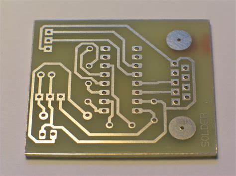
A printed circuit board (PCB) is the backbone of modern electronic devices. It is a flat board made of insulating material, typically fiberglass or composite epoxy, with conductive copper traces etched onto its surface. These traces connect various electronic components mounted on the board, such as resistors, capacitors, integrated circuits, and connectors, forming a complete electronic circuit.
PCBs have revolutionized the electronics industry by providing a reliable and efficient means of assembling electronic devices. They offer several advantages over traditional point-to-point wiring, including:
- Compact size
- Reduced wiring errors
- Improved reliability
- Easier mass production
- Lower manufacturing costs
Understanding the 94V 0 Rating
The “94V 0” rating is a flammability rating for PCB materials, as defined by the Underwriters Laboratories (UL) standard UL94. This standard classifies materials based on their ability to resist ignition and flame spread when exposed to a heat source.
The “94” in the rating refers to the specific UL test method, while the “V” indicates a vertical burn test. The “0” represents the best possible flammability rating, meaning the material is highly resistant to ignition and flame spread.
To achieve a 94V 0 rating, a PCB material must meet the following criteria:
- The material should not burn with flaming combustion for more than 10 seconds after each application of the test flame.
- The total flaming combustion time for 10 flame applications should not exceed 50 seconds.
- The material should not burn with flaming or glowing combustion up to the holding clamp.
- The material should not drip flaming particles that ignite the cotton indicator.
- The material should not have glowing combustion that persists for more than 30 seconds after the second removal of the test flame.

Importance of Flammability Ratings
Flammability ratings are crucial for ensuring the safety and reliability of electronic devices. PCBs are used in a wide range of applications, from consumer electronics to industrial equipment and automotive systems. In many cases, these devices are exposed to high temperatures, electrical surges, or other potential ignition sources.
Using PCB materials with appropriate flammability ratings helps to minimize the risk of fire and protect both the device and its users. The 94V 0 rating is often required for PCBs used in high-reliability applications, such as:
- Medical devices
- Aerospace systems
- Military equipment
- Automotive electronics
- Industrial control systems
By choosing 94V 0 rated PCBs, designers and manufacturers can ensure that their products meet the necessary safety standards and are suitable for use in demanding environments.

Common 94V 0 PCB Materials
Several PCB materials can achieve a 94V 0 flammability rating, each with its own unique properties and advantages. Some of the most common 94V 0 PCB materials include:
FR-4
FR-4 is the most widely used PCB material, consisting of a woven fiberglass cloth impregnated with an epoxy resin. It offers excellent mechanical strength, dimensional stability, and electrical insulation properties. FR-4 is available in various grades, with some specifically designed to meet the 94V 0 flammability rating.
Polyimide
Polyimide is a high-performance polymer known for its exceptional heat resistance, mechanical strength, and dimensional stability. It can maintain its properties at temperatures up to 260°C (500°F), making it suitable for applications that require high-temperature operation. Polyimide PCBs with a 94V 0 rating are often used in aerospace, military, and automotive applications.
Ceramic
Ceramic PCBs are made from a mixture of ceramic powders and organic binders, which are fired at high temperatures to create a dense, rigid substrate. They offer excellent thermal conductivity, low dielectric loss, and high resistance to chemicals and moisture. Ceramic PCBs with a 94V 0 rating are commonly used in high-frequency applications, such as RF and microwave circuits.
PTFE (Teflon)
PTFE, or polytetrafluoroethylene, is a fluoropolymer known for its low Dielectric Constant, low dissipation factor, and high thermal stability. It is an ideal material for high-frequency PCBs, as it minimizes signal loss and distortion. PTFE PCBs with a 94V 0 rating are used in radar systems, satellite communications, and other high-performance applications.

Designing 94V 0 PCBs
When designing PCBs with a 94V 0 flammability rating, several factors must be considered to ensure the board meets the necessary safety standards and performs optimally in its intended application.
Material Selection
The first step in designing a 94V 0 PCB is selecting the appropriate base material. As discussed earlier, several materials can achieve a 94V 0 rating, each with its own advantages and limitations. Designers should consider the specific requirements of their application, such as operating temperature, frequency range, and mechanical stresses, when choosing the base material.
Layer Stack-up
The layer stack-up of a PCB refers to the arrangement of copper layers, insulating layers, and planes within the board. Proper layer stack-up design is crucial for achieving the desired electrical performance and meeting the 94V 0 flammability rating.
Designers should follow these guidelines when creating the layer stack-up for a 94V 0 PCB:
- Use a symmetrical stack-up to minimize warping and ensure even heat distribution.
- Provide adequate spacing between copper layers to prevent electrical shorts and reduce the risk of thermal damage.
- Use appropriate thickness for the insulating layers to maintain the required dielectric strength and minimize the propagation of flames.
- Incorporate thermal relief pads and vias to dissipate heat away from critical components and prevent localized overheating.
Trace Routing
Trace routing is the process of creating the conductive paths that connect the various components on the PCB. When designing traces for a 94V 0 PCB, designers should adhere to the following best practices:
- Use appropriate trace widths and spacing to minimize current densities and prevent overheating.
- Avoid sharp angles and corners in trace routing, as they can create high-stress points and increase the risk of thermal damage.
- Use teardrops at pad-to-trace intersections to reinforce the connection and reduce the risk of pad lifting or trace cracking.
- Incorporate strain relief features, such as curved traces or flexible sections, to accommodate mechanical stresses and prevent trace damage.
Component Placement
Proper component placement is essential for achieving a 94V 0 flammability rating and ensuring the optimal performance of the PCB. Designers should consider the following factors when placing components on the board:
- Group components based on their function and power requirements to minimize trace lengths and reduce the risk of electromagnetic interference (EMI).
- Provide adequate spacing between components to facilitate heat dissipation and prevent thermal interaction.
- Orient components to minimize the impact of mechanical stresses and vibrations.
- Place temperature-sensitive components away from heat sources and high-power components to prevent thermal damage.
Manufacturing 94V 0 PCBs
Once the design of a 94V 0 PCB is complete, the board must be manufactured using processes that ensure the required flammability rating is achieved and maintained throughout the production process.
Material Handling
The first step in manufacturing a 94V 0 PCB is to ensure that the base materials are properly handled and stored to prevent contamination or degradation. The following best practices should be followed:
- Store materials in a clean, dry, and temperature-controlled environment to prevent moisture absorption and maintain their dielectric properties.
- Use appropriate handling equipment and procedures to minimize the risk of mechanical damage or contamination.
- Verify the material certifications and traceability to ensure that the correct 94V 0 rated materials are being used.
Lamination and Curing
The lamination and curing process involves combining the copper layers and insulating layers under heat and pressure to create a solid, rigid PCB substrate. To achieve a 94V 0 rating, the following guidelines should be followed:
- Use a controlled-temperature and pressure lamination process to ensure even heating and minimize the risk of thermal damage.
- Maintain the appropriate curing times and temperatures to ensure that the resin is fully cured and the board achieves its maximum strength and durability.
- Use non-flammable materials for the lamination plates and press pads to prevent the introduction of ignition sources during the lamination process.
Drilling and Plating
After lamination, the PCB must undergo drilling and plating to create the vias and through-holes that connect the different layers of the board. The following best practices should be followed to maintain the 94V 0 flammability rating:
- Use appropriate drill bits and feed rates to minimize the generation of heat and prevent thermal damage to the board.
- Use non-flammable coolants and lubricants during the drilling process to prevent the introduction of ignition sources.
- Plate the vias and through-holes with a non-flammable, high-temperature resistant metal, such as copper or nickel, to ensure adequate conductivity and prevent thermal damage.
Solder Mask and Silkscreen
The solder mask and silkscreen layers are applied to the PCB to protect the copper traces, prevent solder bridging, and provide component identification markings. To maintain the 94V 0 flammability rating, the following guidelines should be followed:
- Use a 94V 0 rated solder mask material that is compatible with the base material and provides adequate coverage and adhesion.
- Apply the solder mask using a controlled-thickness process, such as screen printing or liquid photoimageable coating, to ensure even coverage and minimize the risk of thermal damage.
- Use a 94V 0 rated silkscreen ink that is compatible with the solder mask and provides clear, legible markings.
Testing and Certification
To ensure that a PCB meets the 94V 0 flammability rating, it must undergo rigorous testing and certification by an accredited third-party laboratory. The testing process involves subjecting the PCB to a series of controlled flame exposures and measuring its ability to resist ignition and flame spread.
The following tests are typically performed to certify a PCB as 94V 0 compliant:
- Vertical burning test: The PCB is exposed to a controlled flame for 10 seconds, and the time for the flame to extinguish is measured. The test is repeated 10 times, and the total flaming combustion time must not exceed 50 seconds.
- Drip test: During the vertical burning test, any flaming particles that drip from the PCB must not ignite a cotton indicator placed below the sample.
- Glowing combustion test: After the flame is removed, the PCB must not continue to glow for more than 30 seconds.
If the PCB passes all of these tests, it is certified as 94V 0 compliant and can be marked accordingly.
Advantages of Using 94V 0 PCBs
Using 94V 0 rated PCBs offers several advantages for designers, manufacturers, and end-users, including:
- Enhanced safety: 94V 0 PCBs are highly resistant to ignition and flame spread, minimizing the risk of fire and protecting both the device and its users.
- Improved reliability: By preventing thermal damage and ensuring the integrity of the PCB, 94V 0 materials contribute to the overall reliability and longevity of the electronic device.
- Compliance with industry standards: Many industries, such as aerospace, automotive, and medical, require the use of 94V 0 rated PCBs to ensure compliance with safety regulations and quality standards.
- Versatility: 94V 0 PCBs can be manufactured using a wide range of materials and processes, allowing designers to choose the best option for their specific application and performance requirements.
- Cost-effectiveness: While 94V 0 materials may have a higher initial cost than non-rated alternatives, their enhanced safety and reliability can lead to lower long-term costs by reducing the risk of failures and product recalls.
FAQ
Q1: What does the “94V 0” rating mean for PCBs?
A1: The “94V 0” rating is a flammability rating for PCB materials, as defined by the UL94 standard. It indicates that the material is highly resistant to ignition and flame spread when exposed to a heat source.
Q2: Why is the flammability rating important for PCBs?
A2: Flammability ratings are crucial for ensuring the safety and reliability of electronic devices. PCBs are used in a wide range of applications, and using materials with appropriate flammability ratings helps to minimize the risk of fire and protect both the device and its users.
Q3: What are some common 94V 0 rated PCB materials?
A3: Common 94V 0 rated PCB materials include FR-4, polyimide, ceramic, and PTFE (Teflon). Each material has its own unique properties and advantages, making them suitable for different applications.
Q4: What factors should be considered when designing a 94V 0 PCB?
A4: When designing a 94V 0 PCB, several factors must be considered, including material selection, layer stack-up, trace routing, and component placement. Designers should follow best practices to ensure that the board meets the necessary safety standards and performs optimally in its intended application.
Q5: How are 94V 0 PCBs tested and certified?
A5: To ensure that a PCB meets the 94V 0 flammability rating, it must undergo rigorous testing and certification by an accredited third-party laboratory. The testing process involves subjecting the PCB to controlled flame exposures and measuring its ability to resist ignition and flame spread. If the PCB passes all tests, it is certified as 94V 0 compliant.
Conclusion
94V 0 circuit boards (PCBs) are essential for ensuring the safety and reliability of electronic devices across a wide range of industries. By using materials that are highly resistant to ignition and flame spread, designers and manufacturers can minimize the risk of fire and protect both the device and its users.
Achieving a 94V 0 flammability rating requires careful consideration of material selection, design, manufacturing processes, and testing. By following best practices and adhering to industry standards, designers and manufacturers can create PCBs that meet the necessary safety requirements and perform optimally in their intended applications.
As the demand for high-reliability electronics continues to grow, the importance of 94V 0 PCBs will only increase. By staying up-to-date with the latest materials, technologies, and best practices, designers and manufacturers can ensure that their products are safe, reliable, and compliant with industry standards.


Leave a Reply