What are Impedance Calculators?
Impedance calculators are essential tools for engineers, designers, and technicians working with electrical and electronic systems. These calculators help determine the overall opposition to current flow in an alternating current (AC) circuit, taking into account the effects of resistance, capacitance, and inductance. By accurately calculating impedance, professionals can optimize circuit design, ensure proper system performance, and avoid potential issues such as signal reflections or power loss.
Key Components of Impedance
To understand how impedance calculators work, it is crucial to grasp the three main components that contribute to impedance in an AC circuit:
-
Resistance (R): Resistance is the opposition to current flow caused by the inherent properties of a material. It is measured in ohms (Ω) and is independent of frequency.
-
Capacitance (C): Capacitance is the ability of a component to store electrical charge. In an AC circuit, capacitors impede current flow, and their impedance decreases with increasing frequency. Capacitance is measured in farads (F).
-
Inductance (L): Inductance is the property of a component that opposes changes in current flow. In an AC circuit, inductors impede current flow, and their impedance increases with increasing frequency. Inductance is measured in henries (H).
Types of Impedance Calculators
There are several types of impedance calculators available, each designed to handle specific circuit configurations or applications. Some of the most common types include:
1. Basic Impedance Calculator
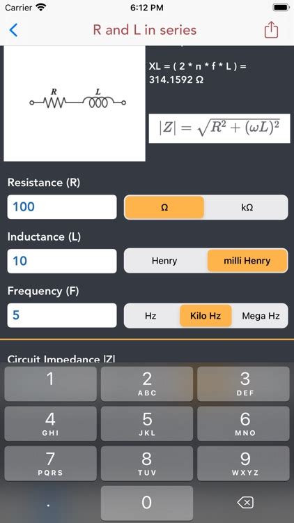
A basic impedance calculator is used to determine the total impedance of a simple series or parallel AC circuit containing resistance, capacitance, and inductance. These calculators typically require users to input the values of R, C, and L, as well as the frequency of the AC signal. The calculator then applies the appropriate mathematical formulas to compute the total impedance.
Example calculation:
For a series RLC circuit with R = 100 Ω, C = 10 µF, L = 50 mH, and f = 1 kHz, the total impedance (Z) is calculated as follows:
Z = √(R² + (XL – XC)²)
where:
– XL = 2πfL = 2π × 1000 Hz × 0.05 H ≈ 314.16 Ω
– XC = 1 / (2πfC) = 1 / (2π × 1000 Hz × 10 × 10⁻⁶ F) ≈ 15.92 Ω
Therefore:
Z = √(100² + (314.16 – 15.92)²) ≈ 316.30 Ω
2. Transmission Line Impedance Calculator
Transmission line impedance calculators are used to determine the characteristic impedance (Z₀) of a transmission line, such as a coaxial cable or a microstrip line. These calculators typically require users to input the physical properties of the transmission line, such as the Dielectric Constant of the insulating material, the diameter of the conductors, and the spacing between them. The calculator then applies the appropriate formulas to compute the characteristic impedance.
Example calculation:
For a coaxial cable with an inner conductor diameter (d) of 1 mm, an outer conductor diameter (D) of 4 mm, and a dielectric constant (ε_r) of 2.3, the characteristic impedance (Z₀) is calculated as follows:
Z₀ = (138 / √ε_r) × log₁₀(D / d)
Therefore:
Z₀ = (138 / √2.3) × log₁₀(4 / 1) ≈ 50.44 Ω
3. Antenna Impedance Calculator
Antenna impedance calculators are used to determine the Input Impedance of an antenna at a specific frequency. These calculators typically require users to input the antenna’s physical dimensions, such as its length and diameter, as well as the frequency of operation. The calculator then applies the appropriate formulas to compute the antenna’s input impedance, which is essential for ensuring proper matching between the antenna and the transmitter or receiver.
Example calculation:
For a half-wave dipole antenna with a length (L) of 1 m and a diameter (d) of 2 mm, operating at a frequency (f) of 150 MHz, the input impedance (Z_in) is approximately:
Z_in ≈ 73 + j42.5 Ω
This value is obtained using complex mathematical formulas and takes into account the antenna’s physical dimensions and the operating frequency.
4. Impedance Matching Calculator
Impedance matching calculators are used to design matching networks that optimize power transfer and minimize signal reflections between a source and a load with different impedances. These calculators typically require users to input the source and load impedances, as well as the desired frequency range. The calculator then suggests various matching network configurations, such as L-networks, Pi-networks, or T-networks, along with the required component values.
Example calculation:
To match a 50 Ω source to a 100 Ω load using an L-network at a frequency of 1 GHz, an impedance matching calculator would suggest the following component values:
- Series inductor (L): 5.6 nH
- Shunt capacitor (C): 1.8 pF
These values are calculated using complex mathematical formulas that take into account the source and load impedances, as well as the desired frequency of operation.

Benefits of Using Impedance Calculators
Using impedance calculators offers several benefits for engineers, designers, and technicians working with electrical and electronic systems:
-
Time-saving: Impedance calculators automate complex mathematical calculations, saving users significant time and effort compared to manual calculations.
-
Accuracy: These calculators use precise formulas and algorithms to ensure accurate results, minimizing the risk of errors that could lead to suboptimal circuit performance or system failures.
-
Optimization: By accurately calculating impedance and designing appropriate matching networks, engineers can optimize power transfer, minimize signal reflections, and improve overall system efficiency.
-
Flexibility: Impedance calculators can handle a wide range of circuit configurations and applications, making them versatile tools for professionals working in various fields, such as telecommunications, RF design, and antenna engineering.
-
Cost-effective: Using impedance calculators can help reduce design and development costs by minimizing the need for physical prototypes and testing, as well as by catching potential issues early in the design process.

Limitations and Considerations
While impedance calculators are powerful tools, users should be aware of their limitations and consider certain factors when using them:
-
Ideal vs. real-world components: Impedance calculators often assume ideal component behavior, which may not always match real-world performance. Users should take into account factors such as component tolerances, parasitic effects, and temperature variations when interpreting results.
-
Frequency-dependent behavior: The impedance of components like capacitors and inductors varies with frequency. Users should ensure that they input the correct frequency values and consider the impact of frequency on the calculated impedance.
-
Complex circuit configurations: While impedance calculators can handle a wide range of circuit configurations, they may not be able to accurately model highly complex or non-standard circuits. In such cases, users may need to rely on more advanced simulation tools or physical measurements.
-
User input errors: The accuracy of impedance calculator results depends on the accuracy of the user’s inputs. Users should double-check their inputs and ensure that they are using the correct units and conventions to avoid errors.

Impedance Calculator Applications
Impedance calculators find applications in a wide range of fields and industries, including:
-
Telecommunications: Impedance calculators are used in the design and optimization of communication systems, such as mobile networks, satellite links, and fiber-optic networks.
-
RF and Microwave Engineering: These calculators are essential for designing and analyzing high-frequency circuits, such as filters, amplifiers, and mixers.
-
Antenna Design: Antenna impedance calculators are used to optimize antenna performance and ensure proper matching between the antenna and the transmitter or receiver.
-
Power Electronics: Impedance calculators are used in the design of power converters, inverters, and switching power supplies to ensure optimal power transfer and minimize losses.
-
Audio Engineering: These calculators are used in the design of audio systems, such as loudspeakers, microphones, and amplifiers, to ensure proper impedance matching and minimize distortion.
FAQ
-
Q: What is the difference between impedance and resistance?
A: Resistance is the opposition to current flow in a direct current (DC) circuit, while impedance is the opposition to current flow in an alternating current (AC) circuit. Impedance takes into account the effects of resistance, capacitance, and inductance, and is frequency-dependent. -
Q: Can impedance calculators handle complex impedances?
A: Yes, many impedance calculators can handle complex impedances, which have both real and imaginary components. These calculators typically display the results in either rectangular (real + j * imaginary) or polar (magnitude ∠ phase angle) form. -
Q: How do I know which type of impedance calculator to use for my application?
A: The choice of impedance calculator depends on the specific circuit configuration or application you are working with. For example, if you are designing a transmission line, you would use a transmission line impedance calculator, whereas if you are working with antennas, you would use an antenna impedance calculator. -
Q: Are impedance calculators always accurate?
A: Impedance calculators are generally accurate when used correctly and with the appropriate inputs. However, users should be aware of the calculators’ limitations and consider factors such as component tolerances, parasitic effects, and frequency-dependent behavior when interpreting results. -
Q: Can I use an impedance calculator for DC circuits?
A: No, impedance calculators are specifically designed for AC circuits. In a DC circuit, only resistance is relevant, and you would use Ohm’s law (V = I * R) to calculate voltage, current, or resistance.
Conclusion
Impedance calculators are invaluable tools for engineers, designers, and technicians working with electrical and electronic systems. By accurately calculating impedance and designing appropriate matching networks, these calculators help optimize circuit performance, minimize signal reflections, and ensure proper power transfer. With a wide range of calculator types available, professionals can find the right tool for their specific application, whether they are working in telecommunications, RF design, antenna engineering, or power electronics.
Despite their many benefits, users should be aware of the limitations of impedance calculators and consider factors such as component tolerances, frequency-dependent behavior, and complex circuit configurations when interpreting results. By using these calculators correctly and in conjunction with other design and analysis tools, engineers can streamline their workflows, reduce costs, and ultimately create more efficient and reliable systems.
As technology continues to advance and the demand for high-performance electrical and electronic systems grows, impedance calculators will remain essential tools for professionals in a wide range of industries. By staying up-to-date with the latest calculator features and best practices, engineers can ensure that they are making the most of these powerful tools and delivering cutting-edge solutions to their clients and customers.


Leave a Reply