What is VHDL used for?
VHDL is primarily used for the design and verification of digital hardware, such as:
- Application-Specific Integrated Circuits (ASICs)
- Field-Programmable Gate Arrays (FPGAs)
- Complex Programmable Logic Devices (CPLDs)
- System-on-Chip (SoC) designs
VHDL allows hardware designers to describe the functionality and structure of digital circuits at various levels of abstraction, from the behavioral level down to the gate level. This enables designers to create, simulate, and verify complex digital systems before committing to physical hardware implementation.
Levels of Abstraction in VHDL
VHDL supports three main levels of abstraction:
-
Behavioral Level: At this level, the designer describes the functionality of the digital system using high-level constructs, such as processes, procedures, and functions. The focus is on the input-output relationship and the overall behavior of the system, without specifying the internal structure or implementation details.
-
Register-Transfer Level (RTL): RTL describes the digital system in terms of registers, combinational logic, and the data flow between them. At this level, the designer specifies the internal structure of the system, including the storage elements (registers) and the logical operations performed on the data.
-
Gate Level: At the gate level, the digital system is described using the basic building blocks of digital circuits, such as AND, OR, NOT, and flip-flops. This level provides the lowest level of abstraction and is closest to the physical implementation of the circuit.
VHDL Language Elements
VHDL consists of several key language elements that allow designers to describe and model digital systems effectively. These elements include:
Entities and Architectures
An entity is the top-level building block in VHDL, representing a module or a component of the digital system. It defines the input and output ports of the module, specifying the interface through which the module communicates with the outside world.
An architecture is associated with an entity and describes the internal functionality and structure of the module. A single entity can have multiple architectures, each representing a different implementation of the same interface.
entity adder is
    port (
        a, b: in std_logic_vector(7 downto 0);
        sum: out std_logic_vector(7 downto 0)
    );
end entity adder;

architecture rtl of adder is
begin
    sum <= a + b;
end architecture rtl;
Signals and Variables
Signals and variables are used to store and propagate data within a VHDL design.
Signals represent wires or connections between components and have a specific data type, such as std_logic or std_logic_vector. Signals are assigned values using the <= operator and have a delayed effect, meaning that the assigned value becomes visible only after a specified time (usually the next simulation cycle).
Variables, on the other hand, are used for temporary storage within a process and are assigned values using the := operator. Variables have an immediate effect, meaning that the assigned value is visible immediately within the process.
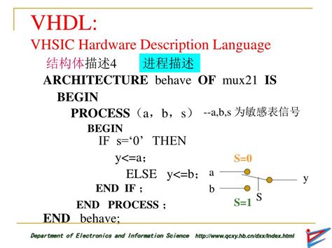
Processes and Concurrency
Processes are the main behavioral units in VHDL and describe the functionality of a digital system. A process is a sequential block of code that is executed when triggered by a specific event, such as a change in a signal value or a clock edge.
VHDL supports concurrency, which means that multiple processes can execute simultaneously, enabling the modeling of parallel behavior in digital systems.
process (clk)
begin
    if rising_edge(clk) then
        -- Sequential logic
        if reset = '1' then
            count <= (others => '0');
        else
            count <= count + 1;
        end if;
    end if;
end process;
Data Types and Operators
VHDL provides a rich set of data types and operators to support the modeling and manipulation of digital data. Some of the commonly used data types include:
std_logicandstd_logic_vector: Used to represent single-bit and multi-bit logic values, respectively.signedandunsigned: Used to represent signed and unsigned integers.integerandreal: Used to represent integer and floating-point numbers.
VHDL also supports a wide range of operators, such as logical operators (and, or, not), arithmetic operators (+, -, *, /), and comparison operators (=, /=, <, <=, >, >=).

VHDL Design Flow
The typical VHDL design flow consists of the following steps:
-
Design Entry: The designer creates the VHDL code using a text editor or an integrated development environment (IDE).
-
Simulation: The VHDL code is simulated using a simulator to verify its functionality and detect any design errors. Test benches are created to provide stimulus to the design and check the outputs against expected results.
-
Synthesis: The VHDL code is synthesized into a gate-level representation using a synthesis tool. The synthesis process maps the VHDL constructs to the physical resources available in the target device (e.g., FPGA or ASIC).
-
Place and Route: The synthesized design is placed and routed onto the target device, taking into account the physical constraints and timing requirements.
-
Verification: The placed and routed design is verified using timing analysis tools to ensure that it meets the specified performance and timing constraints.
-
Programming or Fabrication: For FPGAs, the design is programmed onto the device using a programmer. For ASICs, the design is sent for fabrication.

Advantages of VHDL
VHDL offers several advantages for digital hardware design:
-
Standardization: VHDL is an IEEE standard (IEEE 1076), which ensures compatibility and portability across different tools and platforms.
-
Reusability: VHDL allows for the creation of reusable modules and components, which can be easily integrated into larger designs.
-
Flexibility: VHDL supports multiple levels of abstraction, enabling designers to describe digital systems at the behavioral, RTL, and gate levels.
-
Verification: VHDL provides a powerful simulation and verification environment, allowing designers to test and debug their designs before physical implementation.
-
Collaboration: VHDL facilitates collaboration among hardware designers, as the code can be easily shared, reviewed, and modified by team members.

VHDL vs. Verilog
VHDL and Verilog are the two most widely used hardware description languages in the industry. While both languages serve the same purpose of describing and modeling digital systems, they have some differences in terms of syntax, semantics, and language constructs.
| Feature | VHDL | Verilog |
|---|---|---|
| Standardization | IEEE 1076 | IEEE 1364 |
| Typing | Strongly typed | Weakly typed |
| Syntax | Ada-like syntax | C-like syntax |
| Multilevel Logic | Supported | Limited support |
| File I/O | Supported | Limited support |
| Popularity | Widely used in Europe and defense industry | Widely used in the USA and Asia |
Despite these differences, both VHDL and Verilog are capable of describing and modeling complex digital systems effectively. The choice between the two often comes down to personal preference, company standards, or the requirements of a specific project.
FAQ
-
Q: Is VHDL case-sensitive?
A: Yes, VHDL is a case-insensitive language, meaning that uppercase and lowercase letters are treated as equivalent. However, it is a common convention to use lowercase for keywords and uppercase for user-defined names. -
Q: Can VHDL be used for analog circuit design?
A: While VHDL is primarily used for digital circuit design, it does support the modeling of mixed-signal systems through the use of packages such asstd_logic_1164andstd_logic_arith. However, for full analog circuit design, specialized analog hardware description languages like Verilog-AMS or VHDL-AMS are more suitable. -
Q: What is the difference between a signal and a variable in VHDL?
A: Signals represent wires or connections between components and have a delayed effect, meaning that the assigned value becomes visible only after a specified time (usually the next simulation cycle). Variables, on the other hand, are used for temporary storage within a process and have an immediate effect, meaning that the assigned value is visible immediately within the process. -
Q: Can VHDL be used for system-level design?
A: Yes, VHDL can be used for system-level design through the use of higher levels of abstraction, such as behavioral modeling and register-transfer level (RTL) descriptions. VHDL also supports the modeling of hierarchical systems, where complex designs are broken down into smaller, more manageable modules. -
Q: Is VHDL synthesizable?
A: Not all VHDL constructs are synthesizable, meaning that they cannot be directly mapped to physical hardware. Synthesizable VHDL code is a subset of the language that is restricted to constructs that have a direct hardware equivalent, such as registers, combinational logic, and finite state machines. Non-synthesizable constructs, such as file I/O and certain data types, are used for simulation and verification purposes only.
In conclusion, VHDL is a powerful hardware description language that enables the design, simulation, and verification of complex digital systems. Its standardization, flexibility, and reusability make it an essential tool for hardware designers working on ASICs, FPGAs, and other digital devices. By understanding the key concepts and language elements of VHDL, designers can effectively model and implement digital circuits at various levels of abstraction, from the behavioral level down to the gate level.


Leave a Reply