Introduction to Stripboards and Circuits
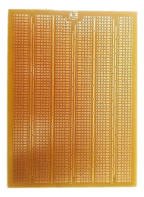
A stripboard, also known as a prototype board or Veroboard, is a printed circuit board (PCB) material with parallel copper strips that are used to create electronic circuits. It allows for quickly and easily building and testing circuit designs without the need for a custom PCB. Stripboards are an essential tool for electronics hobbyists and professionals alike.
Electronic circuits are the foundation of all modern electronics. They consist of interconnected components such as resistors, capacitors, diodes, transistors, and integrated circuits (ICs) that work together to perform a specific function. By arranging these components on a stripboard and making the appropriate connections, you can create a wide variety of circuits for different applications.
Advantages of Using Stripboards
- Quick prototyping: Stripboards enable you to quickly build and test your circuit designs without the need for custom PCB fabrication.
- Cost-effective: Compared to custom PCBs, stripboards are relatively inexpensive, making them ideal for small-scale projects and hobbyists.
- Flexibility: Stripboards allow for easy modification and debugging of circuits, as components can be easily added, removed, or replaced.
- Accessibility: Stripboards are widely available and can be used with a variety of components, making them suitable for both beginners and experienced electronics enthusiasts.
Tools and Materials Needed
To get started with making circuits on a stripboard, you’ll need the following tools and materials:
- Stripboard (Veroboard)
- Soldering iron and solder
- Wire cutters and strippers
- Needle-nose pliers
- Multimeter
- Jumper wires
- Components for your circuit (resistors, capacitors, ICs, etc.)
- Breadboard (optional, for testing before soldering)
Choosing the Right Components
When selecting components for your circuit, it’s essential to consider their specifications and compatibility with your design. Some key factors to keep in mind include:
- Resistance values for resistors
- Capacitance values and voltage ratings for capacitors
- Diode type and forward voltage drop
- Transistor type (NPN or PNP) and maximum ratings
- IC package type (DIP, SOIC, etc.) and pin configuration

Planning Your Circuit Layout
Before you start soldering components to your stripboard, it’s crucial to plan your circuit layout carefully. This will help you avoid mistakes and ensure that your circuit functions as intended.
Creating a Schematic Diagram
The first step in planning your circuit is to create a schematic diagram. A schematic is a visual representation of your circuit that shows how the components are connected. You can use software like KiCad or EasyEDA to create your schematic, or draw it by hand on paper.
| Symbol | Component |
|---|---|
| Resistor | |
| Capacitor | |
| Diode | |
| Transistor | |
| Integrated Circuit (IC) |
Translating Your Schematic to Stripboard Layout
Once you have a schematic, you can start planning how to arrange the components on your stripboard. Consider the following tips:
- Minimize the number of breaks in the copper strips to reduce the complexity of your layout.
- Group related components together to make your circuit easier to understand and debug.
- Leave space between components to avoid short circuits and make soldering easier.
- Use jumper wires to make connections between non-adjacent strips when necessary.

Preparing Your Stripboard
Before soldering your components, you’ll need to prepare your stripboard. This involves cutting the board to size, breaking the copper strips where necessary, and drilling holes for mounting your components.
Cutting the Stripboard to Size
Use a ruler and a pencil to mark the desired size of your stripboard. Make sure to leave enough space for all your components and any additional features like mounting holes. Use a sharp knife or a specialized PCB Cutting tool to carefully cut along the marked lines.
Breaking Copper Strips
To break the copper strips where necessary, use a stripboard cutter or a 3-4mm drill bit. Place the tool at the desired location and apply firm pressure to cut through the copper strip without damaging the surrounding board material.
Drilling Mounting Holes
If your project requires mounting holes, use a drill with a suitable bit size to create them. Be careful not to damage any nearby copper strips or components while drilling.

Soldering Components to the Stripboard
With your stripboard prepared, it’s time to start soldering your components in place. Follow these steps for each component:
- Insert the component leads through the appropriate holes in the stripboard, ensuring that they are in the correct orientation.
- Bend the leads slightly on the underside of the board to hold the component in place.
- Heat up your soldering iron and apply a small amount of solder to the tip to improve heat transfer.
- Touch the soldering iron to the component lead and the copper strip simultaneously, allowing the solder to melt and flow around the joint.
- Remove the soldering iron and let the joint cool for a few seconds before moving on to the next component.
Soldering Tips and Tricks
- Keep your soldering iron clean and well-tinned for better heat transfer and neater joints.
- Use a solder with a suitable diameter for your components and stripboard (e.g., 0.7mm or 1mm).
- Apply heat to the joint for a short time to avoid damaging the components or lifting the copper strips.
- Inspect each joint after soldering to ensure a good connection and correct any errors immediately.
Testing and Debugging Your Circuit
After soldering all your components, it’s crucial to test your circuit to ensure it functions as intended. Follow these steps:
- Visually inspect your stripboard for any short circuits, loose connections, or damaged components.
- Use a multimeter to check for continuity between connected points and verify that there are no unintended connections.
- Power up your circuit using a suitable power supply and check for any signs of malfunction, such as overheating components or unexpected behavior.
- If your circuit doesn’t work as expected, use your schematic and layout diagrams to methodically trace the problem and make any necessary repairs or modifications.
Common Issues and Solutions
| Issue | Possible Causes | Solutions |
|---|---|---|
| No power | – Faulty power supply – Broken connections |
– Check power supply voltage and polarity – Inspect and resolder broken connections |
| Incorrect component behavior | – Wrong component values – Faulty components |
– Double-check component values against schematic – Test components individually and replace if faulty |
| Short circuits | – Solder bridges – Unintended connections |
– Carefully inspect the board and remove solder bridges – Break unintended connections using a knife or PCB cutter |
Advanced Techniques and Considerations
As you become more experienced with making circuits on stripboards, you may want to explore some advanced techniques and considerations:
- Using surface-mount components (SMD) for more compact designs
- Incorporating heatsinks for power-hungry components
- Applying conformal coatings to protect your circuits from moisture and contaminants
- Designing custom stripboard layouts using PCB design software
Troubleshooting Complex Circuits
When working with more complex circuits, troubleshooting can become more challenging. Some tips to help you debug your circuits effectively:
- Break down your circuit into smaller, functional blocks and test each block individually.
- Use a logic analyzer or oscilloscope to observe signals and timing in your circuit.
- Compare your measurements with the expected values from your schematic and datasheets.
- Consult online forums, datasheets, and application notes for guidance on specific components or circuit designs.
Conclusion
Making circuits on a stripboard is a valuable skill for any electronics enthusiast. By understanding the basics of stripboards, planning your layout, and following proper soldering techniques, you can create functional and reliable circuits for a wide range of applications. As you gain more experience, don’t be afraid to experiment with advanced techniques and tackle more complex projects.
FAQ
- Can I use a breadboard instead of a stripboard for my circuit?
-
Yes, breadboards are useful for quickly testing circuit designs before committing them to a stripboard. However, breadboards are not suitable for permanent circuits or projects that require a more robust connection.
-
How do I choose the right wattage for my soldering iron?
-
For most stripboard projects, a soldering iron with a wattage between 30W and 50W is suitable. Higher wattage irons may be necessary for larger components or heavier-gauge wires.
-
What should I do if I accidentally break a copper strip on my stripboard?
-
If the break is small, you can try to bridge the gap with a small piece of wire or a solder blob. For larger breaks, you may need to use a jumper wire to connect the two sections of the strip.
-
Can I reuse components from an old stripboard circuit?
-
Yes, you can desolder components from an old stripboard and reuse them in new projects. However, be careful not to damage the components during the desoldering process, and always test them before using them in a new circuit.
-
How can I make my stripboard circuits more durable?
- To improve the durability of your stripboard circuits, you can apply a conformal coating to protect them from moisture and contaminants. Additionally, using strain relief on wires and cables can help prevent damage from physical stress.


Leave a Reply