Introduction to Potentiometers
A potentiometer, often referred to as a “pot”, is a three-terminal variable resistor that allows you to adjust the resistance between two of its terminals by rotating a knob or sliding a lever. Potentiometers are commonly used for controlling electronic devices, such as adjusting volume, dimming lights, or setting the position of a servo motor.
Potentiometers come in various shapes, sizes, and styles to suit different applications. The most common types are:
- Rotary potentiometers: These have a circular body with a rotating shaft or knob.
- Slider potentiometers: These have a linear track with a sliding knob or lever.
- Trimpots: These are small, preset potentiometers used for fine-tuning circuits.
How a Potentiometer Works
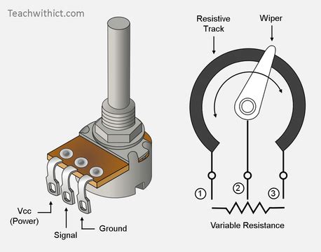
A potentiometer consists of a resistive element, typically a carbon or cermet track, and a wiper that moves along the track. The resistive element is connected to two of the potentiometer’s terminals, while the wiper is connected to the third terminal.
As the wiper moves along the resistive element, it varies the resistance between the wiper terminal and the two end terminals. This allows you to create a variable voltage divider, which can be used to control various electronic devices.
| Terminal | Description |
|---|---|
| 1 | One end of the resistive element |
| 2 | Wiper (moving contact) |
| 3 | Other end of the resistive element |
Understanding Potentiometer Specifications
Before wiring a potentiometer, it’s essential to understand its specifications to ensure compatibility with your project. The main specifications to consider are:
Resistance Value
The resistance value is the total resistance between the two end terminals of the potentiometer. Common values include 1kΩ, 5kΩ, 10kΩ, 50kΩ, 100kΩ, and 1MΩ. Choose a resistance value that suits your application and the devices you’re controlling.
Taper
Taper refers to the relationship between the wiper position and the resistance between the wiper and the end terminals. There are two main types of taper:
-
Linear taper: The resistance changes linearly with the wiper position. This is suitable for applications where a linear response is desired, such as adjusting the position of a servo motor.
-
Logarithmic (audio) taper: The resistance changes logarithmically with the wiper position. This is suitable for applications where a logarithmic response is desired, such as volume control, as it better matches the human ear’s perception of loudness.
Power Rating
The power rating is the maximum power the potentiometer can dissipate without damage. It’s important to choose a potentiometer with a power rating higher than the expected power dissipation in your circuit to prevent overheating and failure.
Physical Size and Mounting Type
Potentiometers come in various physical sizes and mounting types. Common mounting types include:
- Panel mount: These have a threaded bushing and nut for mounting on a panel or chassis.
- PCB mount: These have pins for soldering directly to a printed circuit board (PCB).
Choose a size and mounting type that fits your project’s physical constraints and PCB layout.

Wiring a Potentiometer
Wiring a potentiometer is relatively simple, but it’s important to follow the correct steps to ensure proper operation and avoid damage. The following sections will guide you through the process of wiring potentiometers for different applications.
Basic Potentiometer Wiring
To wire a basic potentiometer, you’ll need the following components:
- Potentiometer
- Wires
- Soldering iron and solder (for PCB-mount potentiometers)
Follow these steps:
-
Identify the potentiometer’s terminals. Refer to the potentiometer’s datasheet or look for markings on the body to locate terminals 1, 2, and 3.
-
Connect wires to the terminals:
- For panel-mount potentiometers, use crimp connectors or solder the wires directly to the terminals.
-
For PCB-mount potentiometers, solder the wires to the pins or solder the potentiometer directly to the PCB.
-
Connect the wires to your circuit according to your application’s requirements. The most common configurations are:
- Variable voltage divider: Connect terminal 1 to the positive voltage supply, terminal 3 to ground, and terminal 2 to the input of the device you’re controlling.
- Rheostat (variable resistor): Connect terminal 1 to one end of your circuit, terminal 3 to the other end, and leave terminal 2 unconnected.
Wiring a Potentiometer for Arduino
Potentiometers are often used with Arduino boards to create interactive projects. Here’s how to wire a potentiometer to an Arduino:
Components needed:
– Arduino board
– Potentiometer (10kΩ recommended)
– Jumper wires
Wiring steps:
- Connect the potentiometer’s terminal 1 to the Arduino’s 5V pin.
- Connect the potentiometer’s terminal 3 to the Arduino’s GND pin.
- Connect the potentiometer’s terminal 2 to one of the Arduino’s analog input pins (e.g., A0).
Here’s an example Arduino sketch that reads the potentiometer’s value and prints it to the serial monitor:
const int potPin = A0;

void setup() {
  Serial.begin(9600);
}

void loop() {
  int potValue = analogRead(potPin);
  Serial.println(potValue);
  delay(100);
}
Wiring Multiple Potentiometers
When wiring multiple potentiometers, it’s essential to consider the total resistance and power dissipation of the circuit. If you’re using potentiometers to create a multi-channel controller, such as a mixer or equalizer, follow these guidelines:
- Choose potentiometers with the appropriate resistance value and taper for each channel.
- Wire each potentiometer as a separate variable voltage divider, with its own positive voltage supply and ground connections.
- Use a common ground for all potentiometers to avoid ground loops and noise.
- If the total current draw of the potentiometers exceeds the rating of your voltage supply, use a separate voltage regulator for the potentiometers.
Here’s an example wiring diagram for a simple 3-channel mixer using potentiometers:
       Channel 1    Channel 2    Channel 3
         Input        Input        Input
          |            |            |
         +-+          +-+          +-+
         | |          | |          | |
         | |          | |          | |
        +-+-+        +-+-+        +-+-+
        |   |        |   |        |   |
        |   |        |   |        |   |
        |  +-+       |  +-+       |  +-+
        +--| |-------+--| |-------+--| |----+
           | |          | |          | |    |
           | |          | |          | |    |
           +-+          +-+          +-+    |
            |            |            |     |
            +------------+------------+-----+
                         |
                       Output

Troubleshooting Potentiometer Wiring
If you encounter issues with your potentiometer wiring, follow these troubleshooting steps:
-
Check for continuity: Use a multimeter to ensure there is continuity between the potentiometer’s terminals and the wires or PCB pads.
-
Verify resistance: Measure the resistance between the potentiometer’s terminals using a multimeter. The resistance between terminals 1 and 3 should match the potentiometer’s rated value, while the resistance between terminal 2 and either end terminal should vary as you adjust the wiper.
-
Check for shorts: Ensure there are no short circuits between the potentiometer’s terminals or between the wires connected to them.
-
Confirm power supply: Verify that the potentiometer is receiving the correct voltage from the power supply. Use a multimeter to measure the voltage between the positive supply and ground.
-
Test with a known-good potentiometer: If you suspect the potentiometer is faulty, replace it with a known-good one to isolate the problem.

FAQ
- What is the difference between a potentiometer and a rheostat?
-
A potentiometer has three terminals and is used as a variable voltage divider, while a rheostat has two terminals and is used as a variable resistor.
-
Can I use a linear taper potentiometer for audio applications?
-
While you can use a linear taper potentiometer for audio applications, a logarithmic (audio) taper potentiometer is recommended for better volume control, as it better matches the human ear’s perception of loudness.
-
How do I determine the power rating of a potentiometer?
-
The power rating is usually specified in the potentiometer’s datasheet. It can also be calculated using the formula: P = V^2 / R, where P is the power rating, V is the voltage across the potentiometer, and R is the potentiometer’s total resistance.
-
Can I wire multiple potentiometers in series?
-
Yes, you can wire potentiometers in series to create a multi-stage voltage divider. However, keep in mind that the total resistance will be the sum of the individual potentiometers’ resistances.
-
How do I control a servo motor with a potentiometer?
- To control a servo motor with a potentiometer, wire the potentiometer as a voltage divider and connect its wiper terminal to an analog input pin on your microcontroller. Use the analog input value to map the potentiometer’s position to the servo motor’s angle using the servo library or custom code.
Conclusion
Potentiometers are versatile components that enable users to control various electronic devices by adjusting resistance. By understanding potentiometer specifications, wiring configurations, and troubleshooting techniques, you can effectively incorporate potentiometers into your projects.
Remember to choose the appropriate resistance value, taper, power rating, and physical size for your application, and follow the wiring guidelines for your specific use case. With proper wiring and implementation, potentiometers can add interactivity and precise control to your electronic projects.


Leave a Reply