Introduction to Nixie Tubes and Clocks
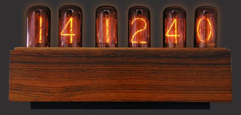
Nixie tubes are an iconic piece of vintage electronics that make for stunning displays. These glass tubes contain a wire-mesh anode and multiple cathodes shaped like numerals or symbols. When a voltage is applied, one of the cathodes lights up with a mesmerizing orange glow.
Nixie tubes were used in electronic equipment from the 1950s to 1970s before being replaced by LEDs and LCDs. However, their unique aesthetic has led to a resurgence in popularity among electronics enthusiasts and makers who incorporate them into custom clocks, thermometers, voltmeters and more.
Building a Nixie Clock is a fun and rewarding project that results in a functional work of art. While many designs use printed circuit boards (PCBs) to simplify wiring, it’s possible to construct a clock without one. This article will walk through the process of building a PCB-free nixie clock from start to finish.
Parts and Tools Needed
To build a nixie clock, you’ll need the following components:
| Part | Quantity |
|---|---|
| IN-14 or IN-16 nixie tubes | 4 |
| K155ID1 nixie driver ICs | 4 |
| 74141 or 74141N BCD-to-decimal decoders | 2 |
| DS3231 or DS1307 real-time clock module | 1 |
| Arduino Nano or similar microcontroller | 1 |
| 5V power supply | 1 |
| 170V DC boost converter | 1 |
| 10kΩ resistors | 4 |
| 22kΩ resistors | 4 |
| 220Ω resistors | 8 |
| 10μF electrolytic capacitors | 4 |
| 0.1μF ceramic capacitors | 4 |
| Rotary encoder with pushbutton | 1 |
| Misc. wire, solder, protoboard, enclosure, etc. | – |
You’ll also need the following tools:
- Soldering iron and solder
- Wire cutters/strippers
- Multimeter
- Arduino IDE software
- Drill and bits (for enclosure)
- Hot glue gun or epoxy

Circuit Design and Schematic
The nixie clock circuitry can be divided into a few main sections:
- Power supply – provides 5V for the microcontroller and logic ICs, and 170V DC for the nixie tubes
- Time base – uses a real-time clock IC to keep accurate time
- Microcontroller – reads the time from the RTC, sets the nixie driver ICs, and handles user input
- BCD to decimal decoders – convert the binary coded decimal (BCD) output from the microcontroller into the discrete lines needed by the nixie drivers
- Nixie drivers and tubes – takes the decoded signals and lights up the numerals on the nixie tubes to display the time
Here is a basic schematic showing how the components are connected:
The nixie power supply boosts the 5V input to the 170V DC needed by the tubes. A simple boost converter module can be used. The nixie driver ICs require a 5V supply.
The real-time clock keeps track of the current time and date. The DS3231 or DS1307 ICs are popular choices that communicate with the microcontroller over I2C. They have a built-in battery backup to maintain time when main power is disconnected.
The Arduino Nano microcontroller is the brains of the operation. It reads the time from the RTC, converts it to BCD format, and sets the appropriate outputs to the decoder and driver ICs. It also reads user input from the rotary encoder to set the time. The Arduino runs off the 5V supply.
The 74141 BCD-to-decimal decoders take the 4-bit BCD signals from the Arduino and activate one of their 10 discrete outputs representing the digits 0-9.
Each nixie tube requires its own K155ID1 driver IC. These take the high-voltage cathode inputs from the decoders and, when enabled, connect them to ground, causing that numeral to glow. The decimal point and leading zero blanking are handled here too. Four nixie tubes and drivers are needed – one for each digit of HH:MM time.
Finally, the rotary encoder lets the user set the current time by scrolling the digits up and down. Pushing the encoder button switches between setting hours and minutes.

Construction
With the circuit designed, it’s time to start building! Let’s break it down step-by-step.
Step 1: Solder tube sockets
The delicate leads of the nixie tubes are not designed for soldering or repeated insertion. Using solder-in tube sockets makes assembly much easier and prevents damage to the tubes.
Choose a socket that matches your tube (IN-14, IN-16, etc). Lay out four sockets on the protoboard and solder them in place, leaving room around them for the driver ICs and other components.
Step 2: Add decoupling capacitors
The nixie tubes and driver ICs are sensitive to power supply noise. Adding decoupling capacitors close to these components stabilizes the voltage.
Solder 0.1μF ceramic capacitors between the power and ground pins of each tube socket. Also add 10μF electrolytic capacitors to the power pins of the nixie driver ICs.
Step 3: Solder K155ID1 nixie drivers
Insert the K155ID1 ICs into the protoboard next to each tube socket. Double check the orientation – the notch or dot should match the schematic.
Solder the IC pins and connect the power pins to the 5V and GND rails. Connect the cathode outputs (pins 1,3,4,5,6,8,9,10,11,15) to the corresponding pins on the tube socket.
Step 4: Wire up 74141 decoders
The 74141 BCD-to-decimal decoders drive the anodes of the nixie tubes. Each one controls two nixie drivers/tubes.
Solder the decoder ICs to the board. Connect the BCD input pins to the Arduino (details below) and the individual outputs to the K155ID1 driver ICs according to the schematic. Use 10kΩ pull-down resistors on the BCD lines.
Step 5: Connect Arduino microcontroller
The Arduino Nano acts as the controller for the clock. Solder male header pins to the protoboard and connect them to the appropriate pins:
| Arduino Pin | Connection |
|---|---|
| 5V | 5V rail, RTC module, encoder |
| GND | GND rail, RTC module, encoder |
| A4 (SDA) | RTC module SDA |
| A5 (SCL) | RTC module SCL |
| D2 | Rotary encoder pin A |
| D3 | Rotary encoder pin B |
| D4 | Rotary encoder button |
| D5 | Minutes BCD bit 0 |
| D6 | Minutes BCD bit 1 |
| D7 | Minutes BCD bit 2 |
| D8 | Minutes BCD bit 3 |
| D9 | Hours BCD bit 0 |
| D10 | Hours BCD bit 1 |
| D11 | Hours BCD bit 2 |
Step 6: Install RTC module
The real-time clock module keeps accurate time for the clock. Connect the 5V, GND, SDA and SCL pins to the Arduino as shown above.
Step 7: Implement rotary encoder
The rotary encoder allows setting the time. Solder the A, B, and button pins to the Arduino as noted previously. The remaining two pins connect to 5V and GND.
Step 8: Wire up power supply
The clock requires two voltages – 5V for the logic and 170V for the tubes. Use a 5V wall adapter or USB power bank for the low voltage. A compact boost converter module generates the high voltage.
Wire the 5V to the protoboard power rails. Connect the boost converter to 5V and GND, and its output to a separate 170V rail for the nixie tubes.

Programming
With the hardware assembled, the clock needs to be programmed to function. The Arduino sketch handles reading the time from the RTC, driving the decoders and nixie tubes, and processing user input from the rotary encoder.
Here are the key components of the code:
- Initialize RTC library and set time if needed
- Read current time from RTC
- Split time into hours and minutes digits
- Convert digits to BCD format
- Output BCD signals to decoder ICs
- Handle rotary encoder interrupts for time setting
- Display current time on nixie tubes
See this example sketch for a complete implementation:
https://pastebin.com/WEWdiuZG
Upload the sketch to the Arduino using the Arduino IDE and USB cable. If all goes well, the clock should display the current time on the nixie tubes!
Finishing Touches
With the electronics functioning, the clock can be mounted in an enclosure. You can design a custom laser-cut acrylic or 3D printed case, or repurpose an existing enclosure like a cigar box or vintage radio.
Lay out the components and drill mounting holes in the case. A rectangular opening in the front displays the nixie tubes. The boost converter and Arduino can be secured with standoffs and screws.
Consider adding a real-time clock backup battery so the time is not lost when unplugged. A CR2032 coin cell battery wired to the appropriate pins on the RTC module will last for years.
For a finishing touch, design and print a custom faceplate with appropriate legends to label the clock. You can create an impressive, personalized look with the right typeface and graphic elements.
Frequently Asked Questions
Can I use different nixie tubes besides IN-14?
Yes, tubes like the IN-12 or IN-16 can also be used. Just make sure to use sockets and voltages specific to your tube. The IN-8-2 is popular for its larger size.
How do I set the time?
Use the rotary encoder to set the hours and minutes. Turning it increments or decrements the selected digit. Pressing the encoder button toggles between hours and minutes mode. The time is saved to the RTC module.
What if I can’t find K155ID1 nixie driver ICs?
The Russian K155ID1 can be difficult to source. You can substitute the 74141 variant which works similarly with slightly different pinout. Alternatively, consider using modern nixie driver ICs like the HV5622.
How much current does a nixie clock draw?
Nixie tubes require around 2.5mA each. The driver ICs and microcontroller use a bit more. Expect the clock to draw 300-500mA in total depending on the size and number of tubes.
Can I add audio or other features?
Definitely! Consider adding a piezo buzzer for chimes or alarms. A thermometer, barometer or voltmeter function can be integrated by choosing a different RTC module. The Arduino has plenty of I/O and processing power for additional functionality.
Conclusion
Building a nixie tube clock is a fantastic way to combine the charm of vintage tech with modern microcontrollers. With a careful design, quality components and some patience, you can create a unique timepiece without the need for a custom PCB.
This project involves working with high voltages, so always observe proper safety precautions. Unplug the clock before modifying circuits, and never touch exposed conductors.
I hope this guide has provided a comprehensive overview of nixie clock design and construction. Feel free to experiment, customize and enhance the basic concept to make it your own. Happy building!


Leave a Reply