What is a Rectifier?
A rectifier is an electrical device that converts alternating current (AC) to direct current (DC). It allows current to flow in only one direction, blocking the reverse flow. Rectifiers are commonly used in power supplies to provide the necessary DC voltage for electronic circuits and devices.
There are several types of rectifiers:
| Rectifier Type | Description |
|---|---|
| Half-wave rectifier | Uses a single diode to allow only one half of the AC waveform to pass |
| Full-wave rectifier | Uses a bridge configuration of four diodes or a center-tapped transformer to rectify both halves of the AC waveform |
| Three-phase rectifier | Uses six or more diodes to rectify three-phase AC power |
| Controlled rectifier (SCR or thyristor) | Allows control of the output voltage by adjusting the phase angle at which the rectifier conducts |
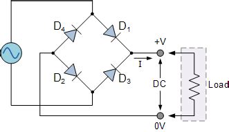
In this guide, we will focus on building a basic full-wave bridge rectifier using diodes.
Components Needed
To build a full-wave bridge rectifier, you will need the following components:
- 4 rectifier diodes (such as 1N4001 or 1N4007)
- 1 transformer (with center tap optional)
- 1 Filter capacitor (value depends on load and ripple requirements, typically 100uF to 10,000uF)
- 1 load resistor (for testing purposes, e.g. 1kΩ)
- Solderless breadboard or printed circuit board (PCB)
- Jumper wires
- AC power source (e.g. wall outlet or function generator)

Step-by-Step Instructions
Step 1: Understand the Schematic
Before building the rectifier, it’s important to understand the schematic diagram:
        +----|>|----+-----|>|----+
AC in   |          |             |
o-------|          |             |-------o DC +
        |          |             |
        +----|<|----+-----|<|----+
                   |
                   |
                   o DC -
The AC input is connected to the transformer, which steps down the voltage to a suitable level. The four diodes are arranged in a bridge configuration, with the anode of each diode connected to the cathode of the adjacent diode. The filter capacitor is connected across the DC output to smooth the ripple.
Step 2: Mount Components
If using a solderless breadboard:
1. Insert the diodes into the breadboard, ensuring correct polarity (cathode band oriented correctly).
2. Place the filter capacitor across the DC output rails, observing polarity.
3. Connect the load resistor across the capacitor.
If using a PCB:
1. Solder the diodes onto the PCB in the bridge configuration.
2. Solder the filter capacitor and load resistor onto the appropriate pads.
Step 3: Connect Transformer
-
If using a center-tapped transformer, connect the center tap to the junction between two diodes on one side of the bridge. Connect the outer leads to the junctions on the other side of the bridge.
-
If using a non-center-tapped transformer, connect one lead to the junction between two diodes on one side, and the other lead to the junction on the opposite side.
Step 4: Apply Power and Test
-
Connect the AC power source to the transformer input. Be cautious, as mains voltage can be dangerous. Use appropriate safety measures.
-
Measure the DC voltage across the load resistor using a multimeter. It should be approximately equal to the peak voltage of the transformer secondary multiplied by 0.9 (due to diode drops).
-
Observe the waveform on an oscilloscope, if available. The output should be a pulsating DC with some ripple, which will be smoothed by the filter capacitor.

Troubleshooting
If the rectifier is not working as expected, consider these troubleshooting steps:
-
Check component polarity: Make sure all diodes and the capacitor are oriented correctly.
-
Verify connections: Ensure all connections are secure and no short circuits are present.
-
Test diodes: Use a multimeter’s diode test function to check each diode for proper forward and reverse bias characteristics.
-
Check transformer output: Measure the AC voltage across the transformer secondary to verify it matches the expected value.
-
Evaluate filter capacitor: If the output ripple is excessive, the filter capacitor may be insufficient or faulty. Try a larger capacitor or a different one.

Safety Considerations
When working with rectifiers and AC power, keep these safety guidelines in mind:
-
Always disconnect power before making circuit changes or adjustments.
-
Use appropriate wire gauges and insulation ratings for the expected currents and voltages.
-
Include fuses or circuit breakers to protect against overcurrent conditions.
-
Consider using isolation transformers or optocouplers for added protection when working with high voltages.
-
Discharge filter capacitors before handling the circuit, as they can store charge even after power is removed.
Applications of Rectifiers
Rectifiers have numerous applications in electronic systems, including:
- DC power supplies for electronic devices
- Battery chargers
- Motor speed controls
- Welding equipment
- Electroplating systems
By understanding the principles and construction of rectifiers, you can harness their capabilities for various projects and applications.
FAQ
1. Can I use any type of diode for a rectifier?
While rectifier diodes are optimized for this application, you can use general-purpose diodes like the 1N4001 series. However, ensure the diode ratings (forward current, reverse voltage) are sufficient for your specific circuit requirements.
2. What happens if I don’t use a filter capacitor?
Without a filter capacitor, the output of the rectifier will be a pulsating DC waveform with significant ripple. The capacitor helps to smooth out the ripple and maintain a more constant DC voltage. The size of the capacitor determines the amount of ripple reduction.
3. Can I use a rectifier to charge a battery?
Yes, rectifiers are commonly used in Battery Charger Circuits. However, additional components like voltage regulators and current limiters are necessary to ensure safe and proper charging. Consult the battery manufacturer’s guidelines for the recommended charging method.
4. How do I select the appropriate transformer for my rectifier?
The transformer should be chosen based on the desired output voltage and current. The transformer secondary voltage should be slightly higher than the desired DC output voltage, accounting for diode drops. The transformer VA rating should exceed the expected load power consumption. Consult transformer datasheets or seek guidance from the manufacturer.
5. Can I parallel multiple rectifiers for higher current output?
Yes, rectifiers can be paralleled to increase the current capacity. However, ensure each rectifier has its own protective fuse and that the diodes are matched for forward voltage drop. Proper load balancing techniques, such as using small balancing resistors, can help distribute the current evenly among the paralleled units.
By following this detailed guide and understanding the principles behind rectifiers, you should be well-equipped to construct and troubleshoot your own Rectifier Circuits. Always prioritize safety and consult additional resources or experts when working with high voltages or unfamiliar components.


Leave a Reply