Introduction to Soldering Methods
Soldering is an essential skill for anyone involved in electronics, whether you’re a hobbyist, a professional technician, or an engineer. Through-hole soldering, in particular, is a widely used technique for connecting electronic components to a printed circuit board (PCB). In this article, we will explore several through-hole soldering methods, their advantages, disadvantages, and best practices to ensure reliable and efficient soldering.
What is Through-Hole Soldering?
Through-hole soldering is a method of attaching electronic components to a PCB by inserting the component leads through pre-drilled holes on the board and soldering them to the copper pads on the opposite side. This technique has been in use for decades and is still popular due to its simplicity, reliability, and the ability to create strong mechanical connections.
Advantages of Through-Hole Soldering
- Strong mechanical connections
- Easy to inspect and repair
- Suitable for high-power components
- Ideal for prototyping and low-volume production
Disadvantages of Through-Hole Soldering
- Requires more space on the PCB compared to surface-mount techniques
- Slower assembly process
- Limited component density

Types of Through-Hole Soldering Methods
There are several through-hole soldering methods, each with its own advantages and disadvantages. The choice of method depends on factors such as the size of the components, the complexity of the circuit, and the available tools and equipment. Let’s explore some of the most common through-hole soldering methods.
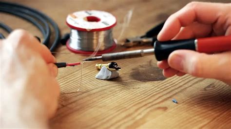
1. Manual Soldering
Manual soldering is the most basic and widely used method for through-hole soldering. It involves using a soldering iron to heat the component lead and the copper pad simultaneously, then applying solder to create a strong electrical and mechanical connection.
Tools and Equipment Required
- Soldering iron
- Soldering iron tip (appropriate size and shape)
- Solder wire (lead-based or lead-free)
- Flux (optional, but recommended)
- Soldering iron stand
- Sponge or brass wool for cleaning the tip
Step-by-Step Guide to Manual Soldering
- Prepare the soldering iron by setting the temperature to the appropriate level (usually between 300°C and 400°C) and cleaning the tip with a damp sponge or brass wool.
- Insert the component leads through the designated holes on the PCB.
- Bend the leads slightly to hold the component in place.
- Apply a small amount of flux to the joint (if using flux-cored solder, this step can be skipped).
- Place the soldering iron tip on the copper pad and the component lead simultaneously.
- Apply solder to the joint, allowing it to melt and flow around the lead and pad.
- Remove the soldering iron and allow the joint to cool and solidify.
- Trim the excess lead close to the joint using wire cutters.
Tips for Successful Manual Soldering
- Use the appropriate soldering iron tip size and shape for the job.
- Maintain the soldering iron tip by keeping it clean and tinned.
- Apply the right amount of heat and solder to create a strong joint without damaging the components.
- Work quickly to minimize the risk of heat damage to the components and PCB.
2. Wave Soldering
Wave soldering is an automated through-hole soldering method commonly used in high-volume production. In this process, the PCB is passed over a molten solder wave, which creates a solder joint on the exposed leads and pads.
Advantages of Wave Soldering
- High-speed process, suitable for mass production
- Consistent solder joint quality
- Reduced labor costs
Disadvantages of Wave Soldering
- High initial setup costs
- Limited flexibility for design changes
- Requires specialized equipment and trained operators
Wave Soldering Process
- PCB Preparation: The PCB is designed with through-hole components and a solder mask to protect areas that should not be soldered.
- Fluxing: The bottom side of the PCB is sprayed with flux to improve solder wettability and prevent oxidation.
- Preheating: The PCB is preheated to activate the flux and minimize thermal shock during soldering.
- Solder Wave Contact: The PCB is passed over a molten solder wave, which creates a solder joint on the exposed leads and pads.
- Cooling: The soldered PCB is cooled to allow the joints to solidify.
- Cleaning: Any remaining flux residue is removed using an appropriate cleaning method.
3. Selective Soldering
Selective soldering is a targeted through-hole soldering method that combines the flexibility of manual soldering with the automation of wave soldering. In this process, a specialized machine applies solder to specific components or areas on the PCB, allowing for the soldering of both through-hole and surface-mount components on the same board.
Advantages of Selective Soldering
- Flexibility to solder specific components or areas
- Suitable for mixed-technology PCBs (through-hole and surface-mount)
- Reduced thermal stress on sensitive components
- Improved solder joint quality compared to manual soldering
Disadvantages of Selective Soldering
- Higher equipment costs compared to manual soldering
- Slower than wave soldering for high-volume production
- Requires programming and setup for each specific PCB design
Selective Soldering Process
- PCB Preparation: The PCB is designed with both through-hole and surface-mount components, and a solder mask is applied to protect areas that should not be soldered.
- Fluxing: The specific areas to be soldered are sprayed with flux to improve solder wettability and prevent oxidation.
- Preheating: The PCB is preheated to activate the flux and minimize thermal shock during soldering.
- Selective Solder Application: A specialized machine applies solder to the specific components or areas using a mini-wave, laser, or solder pot.
- Cooling: The soldered PCB is cooled to allow the joints to solidify.
- Cleaning: Any remaining flux residue is removed using an appropriate cleaning method.

Best Practices for Through-Hole Soldering
Regardless of the soldering method used, following best practices ensures reliable and efficient soldering results. Here are some key considerations:
1. Component Placement
- Ensure components are inserted correctly and securely into the designated holes.
- Maintain proper component orientation and alignment.
- Avoid placing components too close to the edge of the PCB or other components.
2. Solder Joint Quality
- Create a concave solder joint that completely covers the component lead and copper pad.
- Avoid excessive or insufficient solder, as this can lead to weak joints or bridging.
- Ensure the solder joint has a smooth, shiny appearance without any voids or cracks.
3. Thermal Management
- Use the appropriate soldering iron temperature and tip size to minimize heat damage to components and the PCB.
- Avoid applying heat for extended periods, as this can cause component failure or PCB delamination.
- Allow sufficient cooling time between soldering operations to prevent thermal stress.
4. Cleaning and Inspection
- Remove any flux residue using an appropriate cleaning method (e.g., isopropyl alcohol, specialized cleaners).
- Visually inspect solder joints for quality and consistency.
- Use magnification tools, such as a microscope or loupe, for detailed inspection of small components or high-density PCBs.

Frequently Asked Questions (FAQ)
1. What is the difference between lead-based and lead-free solder?
Lead-based solder contains a mixture of tin and lead, typically in a 60/40 or 63/37 ratio. Lead-free solder, on the other hand, is composed of tin and other metals, such as silver and copper. Lead-free solder has a higher melting point and requires slightly different soldering techniques compared to lead-based solder. The use of lead-free solder has become more common due to environmental and health concerns associated with lead.
2. How do I choose the right soldering iron tip for my project?
The choice of soldering iron tip depends on the size and type of components being soldered, as well as the level of precision required. For general through-hole soldering, a chisel or conical tip with a width of 1-3mm is suitable. For smaller components or more precise work, a fine-tipped conical or pencil tip may be more appropriate. It’s a good idea to have a variety of tip sizes and shapes available to accommodate different soldering tasks.
3. What is the purpose of using flux in soldering?
Flux is a chemical compound that helps to improve the wettability of the solder, allowing it to flow more easily and create a stronger bond between the component lead and the copper pad. Flux also helps to remove oxides and other contaminants from the surfaces being soldered, which can interfere with the formation of a good solder joint. Flux can be applied separately or may be included in the core of the solder wire (flux-cored solder).
4. How can I tell if a solder joint is good quality?
A good quality solder joint should have a concave, smooth, and shiny appearance, indicating that the solder has properly wetted the surfaces and created a strong bond. The solder should completely cover the component lead and copper pad, without any gaps, voids, or excessive solder. A good solder joint should also have no visible cracks, pits, or discoloration, which can indicate poor wetting, contamination, or thermal stress.
5. Can I mix different types of solder (e.g., lead-based and lead-free)?
It is generally not recommended to mix different types of solder, as they have different melting points, wetting properties, and mechanical characteristics. Mixing lead-based and lead-free solder can result in inconsistent joint quality and may cause reliability issues over time. If you need to switch between solder types, it’s best to use separate soldering irons and tips to avoid cross-contamination.
Conclusion
Through-hole soldering remains an essential skill for anyone working with electronics, and understanding the various soldering methods and best practices is crucial for creating reliable and efficient solder joints. Whether you’re using manual soldering, wave soldering, or selective soldering, attention to detail, proper technique, and the right tools and materials will help ensure successful soldering results. By following the guidelines and tips outlined in this article, you’ll be well-equipped to tackle a wide range of through-hole soldering projects with confidence.
| Soldering Method | Advantages | Disadvantages |
|---|---|---|
| Manual Soldering | – Flexibility – Low cost – Suitable for prototyping and low-volume production |
– Time-consuming – Requires skilled operators – Inconsistent joint quality |
| Wave Soldering | – High-speed process – Consistent joint quality – Reduced labor costs |
– High initial setup costs – Limited flexibility for design changes – Requires specialized equipment |
| Selective Soldering | – Flexibility to solder specific components or areas – Suitable for mixed-technology PCBs – Improved joint quality compared to manual soldering |
– Higher equipment costs compared to manual soldering – Slower than wave soldering for high-volume production – Requires programming and setup for each PCB design |
By understanding the strengths and weaknesses of each soldering method, you can make informed decisions when selecting the most appropriate approach for your specific project requirements, ensuring a successful outcome and a reliable electronic assembly.


Leave a Reply