What is an Inductor?
An inductor is a passive electronic component that stores energy in the form of a magnetic field. It consists of a coil of wire, typically wrapped around a core made of ferromagnetic material, such as iron or ferrite. The primary function of an inductor is to oppose changes in the current flowing through it, which makes it an essential component in various electronic circuits, such as filters, oscillators, and power supplies.
Key Characteristics of Inductors
- Inductance (L): Measured in henries (H), inductance represents the ability of an inductor to store energy in its magnetic field.
- Current Rating: The maximum current an inductor can handle without overheating or suffering damage.
- Frequency Response: Inductors exhibit different behavior at different frequencies, which is crucial for their application in filters and tuned circuits.
- Quality Factor (Q): The ratio of the inductor’s reactance to its resistance, indicating the efficiency of the inductor.
How Do Inductors Work?
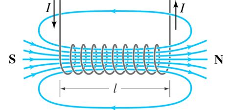
Inductors work on the principle of electromagnetic induction, discovered by Michael Faraday in 1831. When an electric current flows through a conductor, it generates a magnetic field around it. If the current changes, the magnetic field also changes, inducing a voltage in the conductor that opposes the change in current. This phenomenon is known as self-inductance.
In an inductor, the coil of wire acts as the conductor, and the changing current in the coil creates a changing magnetic field. The induced voltage, or back EMF (electromotive force), opposes the change in current, which leads to the inductor’s ability to store energy in its magnetic field and resist changes in current.
Faraday’s Law of Induction
Faraday’s law of induction states that the induced voltage (ε) in a conductor is proportional to the rate of change of the magnetic flux (Φ) through the conductor:
ε = -N * dΦ/dt
Where:
– N is the number of turns in the coil
– dΦ/dt is the rate of change of the magnetic flux
This equation shows that the induced voltage is directly proportional to the number of turns in the coil and the rate of change of the magnetic flux.
Lenz’s Law
Lenz’s law states that the direction of the induced voltage is such that it opposes the change in current that caused it. This means that the induced voltage will always try to maintain the current in the inductor at its present value, resisting any changes in current.

Types of Inductors
There are several types of inductors, each with its own characteristics and applications:
-
Air Core Inductors: These inductors have no core material and consist of a coil of wire wound around a non-magnetic support structure. They have a low inductance value and are suitable for high-frequency applications.
-
Ferrite Core Inductors: These inductors have a core made of ferrite material, which has a high magnetic permeability. They offer higher inductance values and better performance at high frequencies compared to air core inductors.
-
Iron Core Inductors: These inductors have a core made of laminated iron or powdered iron. They provide high inductance values and are suitable for low-frequency applications, such as power supply filters.
-
Toroidal Inductors: These inductors are wound around a donut-shaped core, which can be made of various materials, such as ferrite or powdered iron. They offer high inductance values, low electromagnetic interference (EMI), and compact size.
-
Surface Mount Inductors (SMD): These inductors are designed for surface mount technology (SMT) and are suitable for high-density printed circuit board (PCB) assemblies. They come in various types, such as multilayer, wire-wound, and thin-film inductors.
Comparison of Inductor Types
| Type | Core Material | Inductance Range | Frequency Range | Applications |
|---|---|---|---|---|
| Air Core | None | Low | High | High-frequency circuits, RF tuning |
| Ferrite Core | Ferrite | Medium to High | Medium to High | EMI suppression, power supplies |
| Iron Core | Iron | High | Low | Power supply filters, audio circuits |
| Toroidal | Various | High | Wide range | Power supplies, audio filters |
| Surface Mount (SMD) | Various | Low to Medium | Wide range | High-density PCB Assemblies |

Inductor Applications
Inductors find applications in a wide range of electronic circuits, including:
-
Filters: Inductors are used in various types of filters, such as low-pass, high-pass, and band-pass filters, to attenuate or block specific frequency ranges.
-
Power Supplies: Inductors are essential components in switch-mode power supplies (SMPS), where they are used for energy storage and filtering.
-
Oscillators and Tuned Circuits: Inductors, in combination with capacitors, form LC tanks or tuned circuits that are used in oscillators and radio frequency (RF) circuits.
-
Electromagnetic Interference (EMI) Suppression: Inductors are used to suppress high-frequency noise and EMI in electronic circuits, ensuring proper operation and compliance with electromagnetic compatibility (EMC) standards.
-
Audio Systems: Inductors are used in audio crossover networks, speaker filters, and equalizers to optimize the performance of audio systems.

Inductor Specifications and Selection
When selecting an inductor for a specific application, several key specifications should be considered:
-
Inductance Value: Choose an inductor with the appropriate inductance value for your application, typically specified in henries (H) or microhenries (µH).
-
Current Rating: Ensure that the inductor can handle the expected current in your circuit without overheating or saturating.
-
Frequency Range: Consider the frequency range of your application and choose an inductor that performs well within that range.
-
DC Resistance (DCR): Low DC resistance is desirable to minimize power losses in the inductor.
-
Quality Factor (Q): A higher Q indicates a more efficient inductor with lower losses, which is important for high-frequency applications.
-
Size and Packaging: Select an inductor that fits your PCB layout and packaging requirements, such as through-hole or surface mount.
Inductor Design Considerations
When designing circuits with inductors, several factors should be taken into account:
-
Inductor Placement: Position inductors away from other components that may be sensitive to magnetic fields, such as microcontrollers or sensors.
-
PCB Layout: Minimize the loop area between the inductor and other components to reduce electromagnetic interference (EMI) and improve overall circuit performance.
-
Current Capacity: Ensure that the inductor can handle the expected current without saturating or overheating, which can lead to reduced performance or failure.
-
Shielding: Use shielded inductors or provide adequate shielding around the inductor to minimize EMI and crosstalk with other components.
-
Temperature Effects: Consider the temperature coefficients of the inductor and how they may affect circuit performance over the expected operating temperature range.
Frequently Asked Questions (FAQ)
-
Q: What is the difference between an inductor and a capacitor?
A: While both inductors and capacitors are passive components used in electronic circuits, they store energy in different forms. Inductors store energy in magnetic fields, whereas capacitors store energy in electric fields. Inductors oppose changes in current, while capacitors oppose changes in voltage. -
Q: Can inductors be used in DC circuits?
A: Inductors are primarily used in AC circuits because they rely on changing currents to function. In a pure DC circuit, an inductor acts as a short circuit once the current reaches a steady state. However, inductors are used in DC-DC converters and switching power supplies, where they help in filtering and energy storage during the switching process. -
Q: What is inductor saturation, and why is it important?
A: Inductor saturation occurs when the inductor’s core material reaches its maximum magnetic flux density, and any further increase in current does not result in a corresponding increase in magnetic flux. Saturation leads to a decrease in inductance and an increase in current, which can cause overheating and damage to the inductor. It is essential to choose an inductor with an appropriate current rating and avoid operating it near its saturation point. -
Q: How do I measure the inductance of an inductor?
A: Inductance can be measured using an LCR meter, which is an instrument designed to measure inductance (L), capacitance (C), and resistance (R). Set the LCR meter to the inductance mode, connect the inductor to the meter’s terminals, and read the displayed inductance value. Alternatively, you can use an impedance analyzer or a network analyzer for more advanced measurements. -
Q: Can inductors be connected in series or parallel?
A: Yes, inductors can be connected in series or parallel, depending on the desired inductance value and circuit requirements. When inductors are connected in series, their inductances add up, resulting in a total inductance equal to the sum of the individual inductances. When inductors are connected in parallel, the total inductance is calculated using the reciprocal formula, similar to the way resistors in parallel are calculated.
Conclusion
Inductors are essential components in modern electronic circuits, playing a crucial role in filtering, energy storage, and signal processing. Understanding the basics of inductors, including their working principles, types, and applications, is essential for anyone involved in electronic design or troubleshooting.
By considering factors such as inductance value, current rating, frequency range, and quality factor, you can select the appropriate inductor for your specific application. Additionally, following best practices in inductor placement, PCB layout, and shielding can help optimize circuit performance and minimize potential issues.
As with any electronic component, it is essential to refer to the manufacturer’s datasheets and application notes for detailed specifications and design guidelines. Staying up to date with the latest advancements in inductor technology can also help you make informed decisions when designing or working with electronic circuits.


Leave a Reply