Table of Contents
- Introduction to PCB Drilling
- Types of PCB Drilling
- Mechanical Drilling
- Laser Drilling
- Drilling Machines and Tools
- CNC Drilling Machines
- Drill Bits
- Depth Control Systems
- Drilling Parameters and Considerations
- Drill Bit Selection
- Spindle Speed and Feed Rate
- Hole Accuracy and Tolerance
- Drill Breakout and Deburring
- Challenges in PCB Drilling
- High Aspect Ratio Holes
- Microvias and Blind Vias
- Material Thickness and Stack-up
- Drilling Optimization Techniques
- Drill Path Optimization
- Peck Drilling
- Vacuum Chip Removal
- Quality Control and Inspection
- Visual Inspection
- Automated Optical Inspection (AOI)
- X-Ray Inspection
- Advancements in PCB Drilling Technology
- High-Speed Drilling
- Dual-Spindle Drilling
- Laser-Assisted Drilling
- Environmental and Safety Considerations
- Dust and Debris Management
- Noise Reduction
- Operator Safety
- Frequently Asked Questions (FAQ)
- Conclusion
1. Introduction to PCB Drilling
PCB drilling is a critical process that involves creating holes in a printed circuit board to accommodate component leads, vias, and mounting hardware. The accuracy and precision of these holes directly impact the functionality and reliability of the final electronic device. With the increasing complexity and miniaturization of modern electronics, PCB drilling has become a highly specialized and technologically advanced process.

2. Types of PCB Drilling
There are two primary methods of drilling holes in PCBs: mechanical drilling and laser drilling.
Mechanical Drilling
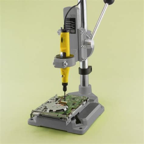
Mechanical drilling is the most common method for creating holes in PCBs. It involves using a drill bit mounted on a high-speed spindle to physically remove material from the board. Mechanical drilling is suitable for a wide range of hole sizes, from large mounting holes to small via holes. The process is relatively fast and cost-effective, making it the preferred choice for most PCB manufacturing applications.
Laser Drilling
Laser drilling is a non-contact method that uses a focused laser beam to vaporize the material and create holes in the PCB. This technique is particularly useful for creating small, high-precision holes, such as microvias and blind vias. Laser drilling offers several advantages over mechanical drilling, including higher accuracy, smaller hole sizes, and the ability to drill non-circular shapes. However, laser drilling is generally more expensive and slower compared to mechanical drilling.

3. Drilling Machines and Tools
To perform PCB drilling effectively, manufacturers rely on specialized machines and tools designed for this purpose.
CNC Drilling Machines
Computer Numerical Control (CNC) drilling machines are the workhorse of the PCB drilling industry. These machines are equipped with high-speed spindles, precision linear motion systems, and advanced control software. CNC drilling machines can automatically position the drill bit and create holes according to the programmed drill file, ensuring high accuracy and repeatability.
Drill Bits
PCB drill bits are specially designed to withstand the rigors of drilling through multiple layers of copper, fiberglass, and other materials used in PCB Construction. They are typically made from tungsten carbide or solid carbide and come in a variety of sizes and geometries to accommodate different hole requirements. The most common drill bit sizes range from 0.2 mm to 6.35 mm in diameter.
| Drill Bit Size (mm) | Typical Application |
|---|---|
| 0.2 – 0.5 | Microvias, high-density interconnects |
| 0.5 – 1.0 | Small component holes, vias |
| 1.0 – 2.5 | Standard component holes |
| 2.5 – 6.35 | Mounting holes, large component holes |
Depth Control Systems
Precise depth control is crucial in PCB drilling to ensure that the holes are drilled to the correct depth without damaging the underlying layers or components. Modern CNC drilling machines incorporate advanced depth control systems, such as laser sensors or touch probes, to accurately measure and control the depth of the drill bit during the drilling process.

4. Drilling Parameters and Considerations
To achieve optimal results in PCB drilling, several key parameters and considerations must be taken into account.
Drill Bit Selection
Selecting the appropriate drill bit for a given application is essential for achieving high-quality holes and maximizing tool life. Factors to consider when choosing a drill bit include the hole size, material thickness, required accuracy, and the specific PCB material being drilled. Drill bit manufacturers provide detailed recommendations and specifications to guide the selection process.
Spindle Speed and Feed Rate
The spindle speed and feed rate are critical parameters that influence the quality and efficiency of the drilling process. Spindle speed refers to the rotational speed of the drill bit, typically measured in revolutions per minute (RPM). Feed rate, on the other hand, is the speed at which the drill bit advances into the material, usually expressed in inches per minute (IPM) or millimeters per minute (mm/min).
The optimal spindle speed and feed rate depend on various factors, such as the drill bit size, material properties, and desired hole quality. Higher spindle speeds and lower feed rates generally produce cleaner and more accurate holes but may result in longer drilling times. Conversely, lower spindle speeds and higher feed rates can increase productivity but may compromise hole quality.
| Drill Bit Size (mm) | Spindle Speed (RPM) | Feed Rate (mm/min) |
|---|---|---|
| 0.2 – 0.5 | 80,000 – 120,000 | 200 – 400 |
| 0.5 – 1.0 | 50,000 – 80,000 | 400 – 800 |
| 1.0 – 2.5 | 30,000 – 50,000 | 800 – 1,500 |
| 2.5 – 6.35 | 10,000 – 30,000 | 1,500 – 3,000 |
Note: The values provided above are general guidelines and may vary depending on the specific material and drilling conditions.
Hole Accuracy and Tolerance
Hole accuracy and tolerance are critical considerations in PCB drilling, as they directly impact the assembly and functionality of the final product. Hole accuracy refers to the deviation of the actual hole position from the intended position specified in the drill file. Tolerance, on the other hand, is the acceptable range of variation in hole size and position.
Typical hole accuracies for PCB drilling range from ±50 μm to ±100 μm, while hole size tolerances are usually specified as ±25 μm to ±50 μm. To achieve these tight tolerances, manufacturers employ high-precision CNC drilling machines, regular calibration, and strict process control measures.
Drill Breakout and Deburring
Drill breakout refers to the phenomenon where the drill bit exits the bottom side of the PCB, often resulting in rough, uneven edges or burrs around the hole. Deburring is the process of removing these burrs and smoothing the hole edges to ensure proper component fit and avoid assembly issues.
There are several techniques used to minimize drill breakout and facilitate deburring, including:
- Using backup material: Placing a sacrificial material beneath the PCB during drilling helps support the drill bit as it exits the board, reducing breakout and burr formation.
- Optimizing drilling parameters: Adjusting the spindle speed, feed rate, and drill bit geometry can help minimize breakout and improve hole quality.
- Deburring tools: Specialized deburring tools, such as abrasive brushes or chamfering bits, are used to remove burrs and smooth hole edges after drilling.
5. Challenges in PCB Drilling
As PCB designs become more complex and feature sizes continue to shrink, manufacturers face several challenges in the drilling process.
High Aspect Ratio Holes
High aspect ratio holes are those with a depth-to-diameter ratio greater than 10:1. Drilling these holes presents unique challenges, as the drill bit is more prone to wandering, breakage, and heat buildup. To overcome these issues, manufacturers employ specialized drill bits with enhanced rigidity, coolant-through designs, and peck drilling techniques.
Microvias and Blind Vias
Microvias are small, high-density interconnects that are typically less than 150 μm in diameter. Blind vias are holes that start at an outer layer and terminate at an inner layer, rather than going through the entire board. Drilling these features requires extreme precision and specialized equipment, such as laser drilling machines or small-diameter mechanical drill bits.
Material Thickness and Stack-up
The thickness and composition of the PCB material stack-up can significantly impact the drilling process. Thicker boards and multi-layer designs with varying material properties may require specialized drilling techniques, such as stepped drilling or controlled-depth drilling, to ensure accurate and reliable holes.
6. Drilling Optimization Techniques
To improve the efficiency and quality of the PCB drilling process, manufacturers employ various optimization techniques.
Drill Path Optimization
Drill path optimization involves strategically planning the sequence and route of the drill bit to minimize drilling time and tool wear. By using intelligent algorithms and CAM software, manufacturers can generate optimized drill paths that reduce unnecessary tool travel and minimize the number of tool changes required.
Peck Drilling
Peck drilling is a technique where the drill bit is repeatedly withdrawn and reinserted into the hole during the drilling process. This allows for chip evacuation, coolant replenishment, and reduces heat buildup in the drill bit. Peck drilling is particularly useful for drilling deep holes or hard materials, as it helps prevent drill bit breakage and improves hole quality.
Vacuum Chip Removal
Vacuum chip removal systems are used to efficiently remove drilling debris and chips from the hole and surrounding area. By continuously evacuating the chips during the drilling process, vacuum systems help prevent chip packing, tool clogging, and ensure clean, burr-free holes.
7. Quality Control and Inspection
Ensuring the quality and consistency of drilled holes is crucial for the overall reliability of the PCB. Manufacturers employ various quality control and inspection techniques to verify hole accuracy, size, and integrity.
Visual Inspection
Visual inspection is the most basic form of quality control, where operators manually examine the drilled holes for visible defects, such as burrs, breakout, or misalignment. This method is useful for catching gross defects but may not detect subtle issues or meet the requirements of high-reliability applications.
Automated Optical Inspection (AOI)
AOI systems use high-resolution cameras and advanced image processing algorithms to automatically inspect drilled holes for defects and measure critical dimensions. AOI can quickly and accurately detect issues such as hole size variation, misalignment, and missing or extra holes. This method is particularly useful for high-volume production and ensures consistent quality across multiple boards.
X-Ray Inspection
X-ray inspection is a non-destructive testing method that allows manufacturers to examine the internal structure of the PCB, including the drilled holes and vias. This technique is particularly useful for inspecting buried or blind vias, as well as detecting issues such as voids, delamination, or plating defects that may not be visible from the surface.
8. Advancements in PCB Drilling Technology
As the electronics industry continues to evolve, PCB drilling technology is advancing to keep pace with the increasing demands for smaller, faster, and more reliable devices.
High-Speed Drilling
High-speed drilling machines are designed to operate at spindle speeds of up to 300,000 RPM, enabling faster drilling times and improved hole quality. These machines often incorporate advanced features such as linear motors, air bearings, and high-frequency spindles to achieve the necessary speed and precision.
Dual-Spindle Drilling
Dual-spindle drilling machines feature two independent spindles that can drill holes simultaneously, effectively doubling the throughput compared to single-spindle machines. This technology is particularly beneficial for high-volume production or boards with a large number of holes.
Laser-Assisted Drilling
Laser-assisted drilling combines the advantages of mechanical drilling and laser drilling by using a laser to pre-condition the material before the mechanical drill bit engages. This technique helps reduce the force required for drilling, minimizes drill wander, and improves hole quality, particularly in challenging materials or high aspect ratio applications.
9. Environmental and Safety Considerations
PCB drilling processes generate dust, debris, and noise that can have an impact on the environment and operator safety. Manufacturers must implement appropriate measures to mitigate these concerns.
Dust and Debris Management
Drilling operations produce fine dust particles and chips that can pose health risks if inhaled and may contaminate the workspace. To address this issue, manufacturers use vacuum systems and air filtration units to capture and safely dispose of the drilling debris. Regular cleaning and maintenance of the work area also help minimize the accumulation of dust and chips.
Noise Reduction
The high-speed operation of drilling machines can generate significant noise levels that may be harmful to operators and disruptive to the work environment. Manufacturers employ various noise reduction strategies, such as enclosing the drilling machines in soundproof cabinets, using vibration-damping materials, and providing operators with appropriate hearing protection.
Operator Safety
Ensuring the safety of drilling machine operators is of utmost importance. Manufacturers must provide adequate training, personal protective equipment (PPE), and implement safety protocols to prevent accidents and minimize the risk of injury. This includes measures such as guarding moving parts, implementing emergency stop systems, and adhering to proper machine maintenance and operation procedures.
10. Frequently Asked Questions (FAQ)
-
What is the smallest hole size that can be drilled in a PCB?
The smallest hole size that can be drilled in a PCB depends on the drilling method and the capabilities of the drilling machine. With advanced mechanical drilling machines and specialized drill bits, holes as small as 0.1 mm (100 μm) in diameter can be achieved. Laser drilling can produce even smaller holes, down to 50 μm or less. -
How does the PCB material affect the drilling process?
The type of PCB material can significantly impact the drilling process. Different materials, such as FR-4, Rogers, or polyimide, have varying hardness, thermal properties, and machinability. Harder materials may require slower feed rates, higher spindle speeds, and more frequent tool changes to maintain hole quality and prevent drill bit wear. Some materials, like ceramic substrates, may require specialized drilling techniques or diamond-coated drill bits. -
What is the difference between plated and non-plated holes in a PCB?
Plated holes are drilled holes that have a thin layer of conductive material, typically copper, deposited on the hole walls. This plating process creates an electrical connection between the layers of the PCB, allowing signals to pass through the board. Non-plated holes, also known as tooling holes or mounting holes, do not have any conductive plating and are used for mechanical purposes, such as securing the PCB to an enclosure or aligning the board during assembly. -
How often should PCB drill bits be replaced?
The frequency of drill bit replacement depends on several factors, including the material being drilled, the hole size, and the drilling parameters. As a general guideline, drill bits should be replaced when they show signs of wear, such as reduced cutting performance, increased drilling time, or poor hole quality. Manufacturers typically establish a drill hit count or a tool life expectancy based on their specific process requirements and experience. Regular inspection and tracking of drill bit performance can help optimize tool life and maintain consistent hole quality. -
Can PCB drilling be performed in-house, or is it better to outsource?
The decision to perform PCB drilling in-house or outsource it to a specialized manufacturer depends on several factors, such as production volume, board complexity, and available resources. In-house drilling can provide greater control over the process, faster turnaround times, and the ability to handle custom or prototype designs. However, it requires significant investment in equipment, trained personnel, and quality control measures. Outsourcing to a PCB drilling service provider can be more cost-effective for high-volume production or complex designs that require specialized equipment and expertise. It also allows companies to focus on their core competencies and avoid the overhead costs associated with maintaining an in-house drilling operation.
11. Conclusion
PCB drilling is a critical process that directly impacts the quality, reliability, and functionality of electronic devices. As PCB designs continue to evolve and push the boundaries of miniaturization and performance, drilling technologies and techniques must keep pace to meet these challenges. From high-speed mechanical drilling to laser-assisted processes, manufacturers have a wide range of tools and strategies at their disposal to create precise, high-quality holes in PCBs.
By understanding the various aspects of PCB drilling, including drilling methods, machines, tools, and optimization techniques, manufacturers can make informed decisions and implement best practices to improve their drilling processes. Additionally, by prioritizing quality control, environmental responsibility, and operator safety, companies can ensure that their PCB drilling operations are not only efficient and reliable


Leave a Reply