Introduction to CadSoft EAGLE
CadSoft EAGLE is a powerful and user-friendly PCB design software that has been widely used by engineers, hobbyists, and students for over two decades. EAGLE, which stands for “Easily Applicable Graphical Layout Editor,” offers a comprehensive suite of tools for designing electronic circuits and creating professional-grade PCBs. In this article, we will explore the features and benefits of CadSoft EAGLE V7, the latest version of this popular software.
What is CadSoft EAGLE?
CadSoft EAGLE is an electronic design automation (EDA) software that allows users to create schematic diagrams, design PCB layouts, and generate manufacturing files for their electronic projects. The software is known for its intuitive interface, extensive component libraries, and powerful routing capabilities, making it an ideal choice for both beginners and experienced designers.
Key Features of CadSoft EAGLE V7
-
Schematic Editor: EAGLE’s schematic editor allows users to create and edit electronic Circuit Diagrams using a wide range of components from the built-in libraries or custom-made parts.
-
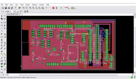
PCB Layout Editor: The PCB layout editor enables users to design single-sided, double-sided, or Multi-layer PCBs with ease. It offers a variety of routing tools, design rule checks (DRC), and automatic placement options to streamline the PCB design process.
-
Library Management: EAGLE comes with an extensive library of components, including resistors, capacitors, ICs, and connectors. Users can also create their own custom libraries or modify existing ones to suit their specific needs.
-
Autorouter: The software includes an advanced autorouter that can automatically route traces on the PCB based on user-defined design rules and constraints, saving time and effort in the layout process.
-
3D Visualization: EAGLE V7 introduces a new 3D visualization feature that allows users to view their PCB designs in a realistic, three-dimensional representation. This helps in identifying potential issues and ensuring proper component placement.
-
ULP (User Language Program) Support: EAGLE supports User Language Programs, which are scripts written in a simple programming language that can automate repetitive tasks and extend the functionality of the software.
Getting Started with CadSoft EAGLE
System Requirements
Before installing CadSoft EAGLE, ensure that your computer meets the following minimum system requirements:
| Operating System | Processor | RAM | Free Disk Space |
|---|---|---|---|
| Windows 7/8/10 | 1 GHz | 2 GB | 500 MB |
| macOS 10.11 or later | 1 GHz | 2 GB | 500 MB |
| Linux (64-bit) | 1 GHz | 2 GB | 500 MB |
Installation Process
-
Download the appropriate version of CadSoft EAGLE for your operating system from the official website or a trusted source.
-
Run the installer and follow the on-screen instructions to complete the installation process.
-
Launch CadSoft EAGLE and activate the software using a valid license key or choose the freeware version for non-commercial use.
Creating a New Project
To create a new project in CadSoft EAGLE, follow these steps:
-
Click on “File” in the main menu and select “New Project.”
-
Choose a location to save your project and give it a meaningful name.
-
In the “Project” window, right-click on the project name and select “New” to create a new schematic or board file.
-
Start designing your electronic circuit in the schematic editor or PCB layout editor.

Designing Schematics in CadSoft EAGLE
Adding Components
To add components to your schematic:
-
Click on the “Add” tool in the schematic editor toolbar.
-
Browse through the available libraries to find the desired component, or search for it using the search function.
-
Click on the component to select it and then click on the schematic canvas to place it.
-
Repeat the process to add more components to your schematic.
Wiring Components
To connect components in your schematic:
-
Click on the “Net” tool in the schematic editor toolbar.
-
Click on the first pin or connection point you want to wire.
-
Move the cursor to the second pin or connection point and click to complete the connection.
-
Continue wiring components until your circuit is complete.
Assigning Values and Packages
To assign values and packages to your components:
-
Double-click on a component to open its properties window.
-
In the “Value” field, enter the appropriate value for the component (e.g., resistance, capacitance, or IC part number).
-
In the “Package” field, select the appropriate physical package for the component from the available options.
-
Click “OK” to apply the changes.

Designing PCBs in CadSoft EAGLE
Creating a Board from a Schematic
To create a PCB layout from your schematic:
-
Click on the “Board” icon in the schematic editor toolbar to switch to the PCB layout editor.
-
If prompted, choose “Yes” to create a new board from the schematic.
-
EAGLE will automatically place the components on the board and create airwires (virtual connections) between them.
Placing Components
To place components on your PCB:
-
Use the “Move” tool to select and reposition components on the board.
-
Pay attention to component orientation and ensure proper spacing between components to avoid interference and manufacturing issues.
-
Use the “Rotate” tool to change the orientation of components if necessary.
Routing Traces
To route traces on your PCB:
-
Click on the “Route” tool in the PCB layout editor toolbar.
-
Set the appropriate trace width and clearance settings in the “Route” toolbar.
-
Click on the starting pad or via and move the cursor to the ending pad or via, following the desired path for the trace.
-
Click to place the trace segments and continue routing until all connections are complete.
-
Use the “Ripup” tool to remove any unwanted traces or segments.
Design Rule Checks (DRC)
To ensure your PCB design adheres to manufacturing constraints and guidelines:
-
Click on “Tools” in the main menu and select “DRC…”
-
Configure the design rules according to your PCB Manufacturer’s specifications, such as minimum trace width, clearance, and hole sizes.
-
Click “Check” to run the DRC and identify any rule violations.
-
Address the reported issues by modifying your PCB layout as needed.

Generating Manufacturing Files
Gerber Files
To generate Gerber files for PCB manufacturing:
-
Click on “File” in the main menu and select “CAM Processor.”
-
In the CAM Processor window, select “gerber_rs274x” from the “Device” dropdown menu.
-
Configure the output settings, such as file format and layer selection, according to your PCB manufacturer’s requirements.
-
Click “Process Job” to generate the Gerber files.
Drill Files
To generate drill files for PCB manufacturing:
-
In the CAM Processor window, select “excellon” from the “Device” dropdown menu.
-
Configure the output settings, such as drill unit and hole sizes, according to your PCB manufacturer’s requirements.
-
Click “Process Job” to generate the drill files.
Frequently Asked Questions (FAQ)
-
Is CadSoft EAGLE free to use?
CadSoft EAGLE offers a freeware version for non-commercial use, which has limitations on board size and layer count. For commercial use or access to advanced features, a paid license is required. -
Can I import designs from other EDA software into CadSoft EAGLE?
Yes, CadSoft EAGLE supports importing design files from various EDA software, such as Altium Designer, KiCad, and OrCAD. You can use the “Import” function in the File menu to bring in external designs. -
Does CadSoft EAGLE have a built-in simulation tool?
No, CadSoft EAGLE does not have a built-in simulation tool. However, you can export your schematic to a SPICE format and use external simulation software, such as LTspice or PSpice, to perform circuit simulations. -
Can I create custom component libraries in CadSoft EAGLE?
Yes, CadSoft EAGLE allows you to create custom component libraries. You can use the Library Editor to create new components or modify existing ones to suit your specific requirements. -
What file formats can I export my PCB designs to?
CadSoft EAGLE supports exporting PCB designs to various file formats, including Gerber (RS-274X), Excellon drill, AutoCAD DXF, and Siemens ODB++. These files can be used for PCB manufacturing or integration with other CAD software.
Conclusion
CadSoft EAGLE V7 is a powerful and versatile PCB design software that offers a comprehensive set of tools for creating electronic circuits and PCBs. With its intuitive interface, extensive component libraries, and advanced features, EAGLE is an excellent choice for both beginners and experienced designers. By following the steps outlined in this article, you can quickly get started with CadSoft EAGLE and bring your electronic projects to life.
As you continue to explore and use CadSoft EAGLE, you will discover its many capabilities and learn to leverage its features to create professional-grade PCBs. With a strong community of users and a wealth of online resources, you can find support, inspiration, and guidance as you develop your PCB design skills.
So, whether you are a hobbyist working on a personal project or an engineer designing complex electronic systems, CadSoft EAGLE V7 provides the tools and flexibility you need to turn your ideas into reality. Start designing your next PCB today and experience the power and ease of use that CadSoft EAGLE has to offer.


Leave a Reply