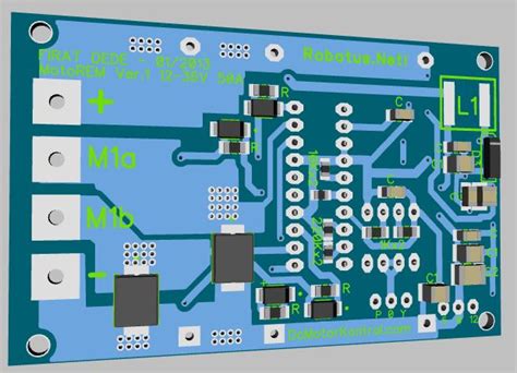
Introduction to Motor PCB Optimization
Printed Circuit Boards (PCBs) play a crucial role in motor control systems, especially when dealing with high current applications. Optimizing the PCB design for motor controls is essential to ensure reliable performance, efficient power delivery, and minimal losses. In this article, we will explore various techniques and considerations for optimizing high current PCBs for motor controls.
Understanding the Challenges of High Current Motor PCBs
Current Density and Thermal Management
One of the primary challenges in designing high current motor PCBs is managing the current density and thermal dissipation. As current flows through the PCB traces, it generates heat due to the resistance of the copper. The higher the current, the more heat is generated, which can lead to thermal stress and potential failure of the PCB if not properly managed.
To address this challenge, designers must consider the following factors:
– Trace width and thickness: Wider and thicker traces have lower resistance and can handle higher currents with less heat generation.
– Copper weight: Using higher copper weights (e.g., 2 oz or 4 oz) can further reduce resistance and improve current carrying capacity.
– Thermal relief: Incorporating thermal relief pads around high-current components helps dissipate heat more effectively.
– Heatsinks and cooling: Using heatsinks and active cooling methods, such as fans or liquid cooling, can help dissipate heat from critical components.
EMI and Noise Reduction
High current motor control PCBs are prone to electromagnetic interference (EMI) and noise due to the switching nature of the power electronics and the high-frequency components involved. EMI can cause disruptions in the motor control system and affect nearby electronic devices.
To minimize EMI and noise, consider the following techniques:
– Proper grounding: Implement a solid ground plane and use star grounding techniques to minimize ground loops and reduce noise.
– Shielding: Use shielding techniques, such as grounded copper pours or shielding cans, to contain EMI generated by high-frequency components.
– Filtering: Incorporate appropriate filtering components, such as capacitors and ferrite beads, to suppress high-frequency noise.
– Component placement: Carefully place components to minimize the loop area and reduce the coupling of noise between different sections of the PCB.

PCB Layout Considerations for Motor Controls
Power and Ground Planes
Using dedicated power and ground planes is crucial for high current motor control PCBs. These planes provide low-impedance paths for current flow and help distribute the current evenly across the PCB. They also act as shields against EMI and reduce the inductance of the power delivery network.
When designing power and ground planes, consider the following:
– Plane thickness: Use thicker copper layers for power and ground planes to minimize resistance and improve current carrying capacity.
– Plane separation: Maintain adequate separation between power and ground planes to reduce capacitive coupling and minimize noise.
– Via placement: Place vias strategically to provide low-impedance connections between layers and ensure efficient current flow.
Component Placement and Routing
Proper component placement and routing are essential for optimizing high current motor control PCBs. Consider the following guidelines:
– Power components: Place power components, such as MOSFETs and diodes, close to the power input and output connectors to minimize trace lengths and reduce losses.
– Decoupling capacitors: Place decoupling capacitors as close as possible to the power pins of ICs to minimize the loop area and provide effective decoupling.
– Sensitive signals: Route sensitive signals, such as feedback and control signals, away from high-current paths to avoid interference.
– Trace width and spacing: Use appropriate trace widths based on the current requirements and maintain adequate spacing between traces to prevent crosstalk and EMI.
Thermal Management Techniques
Effective thermal management is crucial for high current motor control PCBs. In addition to the techniques mentioned earlier, consider the following:
– Copper pours: Use large copper pours on the PCB to create a heat-spreading effect and improve thermal dissipation.
– Thermal vias: Use thermal vias to transfer heat from the components to the other side of the PCB or to the heatsink.
– Component selection: Choose components with low thermal resistance and high power handling capabilities to minimize heat generation.
– Thermal interface materials: Use thermal interface materials, such as thermal pads or thermal grease, to improve heat transfer between components and heatsinks.

Simulation and Testing
Thermal Simulation
Conducting thermal simulations during the PCB design process can help identify potential hot spots and optimize the thermal management strategy. Thermal simulation tools allow designers to analyze the temperature distribution across the PCB and make necessary adjustments before fabrication.
EMI Simulation
EMI simulations can help predict and mitigate potential EMI issues in high current motor control PCBs. These simulations can identify problematic areas and guide the design of shielding and filtering solutions.
Prototype Testing
Building and testing prototypes is essential to validate the PCB design and ensure its performance meets the requirements. During prototype testing, consider the following:
– Current handling: Test the PCB under various load conditions to verify its current handling capability and identify any potential weaknesses.
– Thermal performance: Monitor the temperature of critical components and PCB areas to ensure they remain within acceptable limits.
– EMI testing: Conduct EMI testing to verify that the PCB complies with relevant EMC standards and does not cause interference to other electronic devices.

Best Practices for High Current Motor PCB Design
Component Selection
Choosing the right components is crucial for optimizing high current motor control PCBs. Consider the following factors when selecting components:
– Current rating: Select components with sufficient current rating to handle the expected load currents with a safety margin.
– Thermal characteristics: Choose components with low thermal resistance and good heat dissipation capabilities.
– Packaging: Consider using components with packages that facilitate heat transfer, such as TO-220 or D-PAK.
Trace Width Calculation
Calculating the appropriate trace width is essential to ensure the PCB can handle the required current without excessive heating. Use the following formula to estimate the trace width:
Trace Width (mm) = (Current (A) × Trace Thickness (oz) × 0.0254) / (Temperature Rise (°C) × Trace Length (mm))
Where:
– Current (A) is the maximum expected current through the trace.
– Trace Thickness (oz) is the copper weight of the trace (e.g., 1 oz, 2 oz).
– Temperature Rise (°C) is the maximum allowed temperature rise above ambient.
– Trace Length (mm) is the length of the trace.
Parallelization of Traces
For high current applications, paralleling multiple traces can help distribute the current and reduce the overall resistance. When parallelizing traces, ensure that the traces are of equal length to maintain equal current distribution and avoid current crowding.
Copper Plating Techniques
Copper plating techniques can enhance the current carrying capacity and thermal performance of PCB traces. Consider the following techniques:
– Copper thieving: Adding copper thieving patterns around high-current traces helps distribute the current more evenly and reduces the risk of hot spots.
– Via stitching: Using via stitching along high-current traces provides additional paths for current flow and improves thermal dissipation.
Frequently Asked Questions (FAQ)
-
What is the impact of increasing the copper weight on high current motor PCBs?
Answer: Increasing the copper weight of PCB traces reduces their resistance, allowing them to handle higher currents with less heat generation. Doubling the copper weight (e.g., from 1 oz to 2 oz) can significantly improve the current carrying capacity and thermal performance of the PCB. -
How does thermal management affect the reliability of high current motor control PCBs?
Answer: Proper thermal management is essential for the reliability of high current motor control PCBs. Excessive heat can lead to component failure, PCB Delamination, and reduced lifespan. By implementing effective thermal management techniques, such as using heatsinks, thermal vias, and copper pours, designers can ensure that the PCB operates within safe temperature limits and maintains reliable performance over its intended lifetime. -
What are the benefits of using a four-layer PCB for high current motor control applications?
Answer: Using a four-layer PCB for high current motor control applications offers several benefits: - Dedicated power and ground planes: The inner layers can be used as dedicated power and ground planes, providing low-impedance paths for current flow and reducing noise.
- Better EMI performance: The additional layers allow for better shielding and grounding, reducing EMI and improving the overall noise performance of the PCB.
-
Improved thermal management: The additional copper layers help spread heat more effectively, leading to better thermal dissipation and lower component temperatures.
-
How can component placement optimization reduce EMI in high current motor control PCBs?
Answer: Optimizing component placement can significantly reduce EMI in high current motor control PCBs. By placing components strategically, designers can minimize the loop area between high-current paths and sensitive signals, reducing the coupling of noise. Additionally, placing decoupling capacitors close to the power pins of ICs helps minimize the power supply loop and suppress high-frequency noise. -
What are the advantages of using thermal simulation during the PCB design process?
Answer: Thermal simulation offers several advantages during the PCB design process: - Identifying hot spots: Thermal simulations help identify potential hot spots on the PCB, allowing designers to make necessary adjustments before fabrication.
- Optimizing thermal management: By simulating different thermal management strategies, designers can determine the most effective approach for their specific application.
- Reducing design iterations: Thermal simulations can help minimize the number of design iterations required, saving time and cost in the development process.
- Ensuring reliability: By verifying the thermal performance of the PCB through simulations, designers can ensure that the final product will operate reliably within the specified temperature range.
Conclusion
Optimizing high current PCBs for motor controls requires careful consideration of various factors, including current density, thermal management, EMI reduction, and PCB layout. By following best practices, such as using appropriate trace widths, implementing effective thermal management techniques, and optimizing component placement, designers can create reliable and efficient motor control PCBs that meet the demands of high current applications.
Through the use of simulation tools, prototype testing, and adherence to design guidelines, engineers can overcome the challenges associated with high current PCB design and develop robust motor control systems. By continuously refining and improving PCB designs, the performance and reliability of motor control applications can be enhanced, leading to better overall system efficiency and longevity.


Leave a Reply