What is a Bed-of-Nails Test?
A bed-of-nails test, also known as a bed-of-pins test or a fixture test, is a method used in electrical testing to verify the functionality and quality of printed circuit boards (PCBs) and electronic assemblies. This test involves using a specialized test fixture that contains an array of spring-loaded pins, which make contact with specific test points on the PCB or assembly under test (AUT). The bed-of-nails test is an essential part of the manufacturing process, ensuring that the PCBs and assemblies meet the required specifications and are free from defects before they are assembled into the final product.
How Does a Bed-of-Nails Test Work?
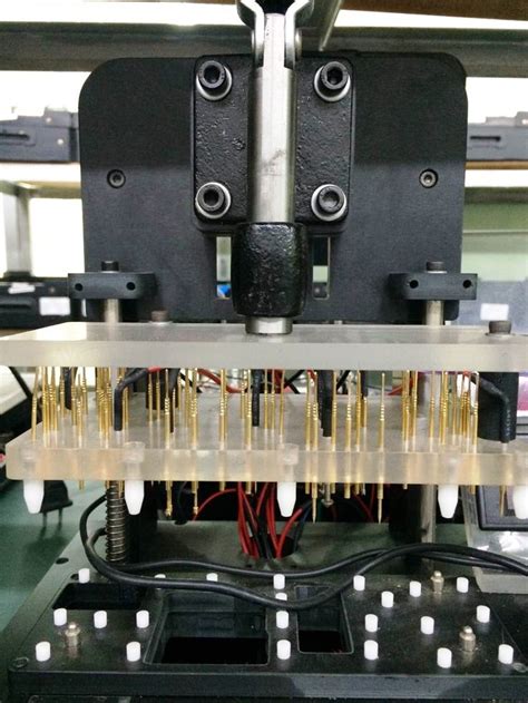
The bed-of-nails test fixture consists of a base plate with an array of pins arranged in a pattern that matches the test points on the PCB or assembly. The pins are typically made of gold-plated spring-loaded contacts that ensure reliable electrical connections with the test points. The test fixture is connected to a computer-controlled test system, which applies electrical signals to the test points and measures the responses to determine the functionality and quality of the AUT.
The test system typically includes the following components:
1. Test fixture with spring-loaded pins
2. Interconnect cables
3. Switching matrix
4. Measurement instruments (e.g., digital multimeters, oscilloscopes, signal generators)
5. Computer with test software
During the test, the AUT is placed on the test fixture, and the pins make contact with the test points. The test system then applies a series of electrical signals to the test points and measures the responses. The test software compares the measured values with the expected values to determine if the AUT meets the required specifications.
Advantages of Bed-of-Nails Testing
Bed-of-nails testing offers several advantages over other testing methods, such as:
- High throughput: Bed-of-nails testing allows for rapid testing of multiple test points simultaneously, enabling high-volume production testing.
- Repeatability: The test fixture ensures consistent and repeatable testing, minimizing the likelihood of human error.
- Accuracy: The spring-loaded pins provide reliable electrical connections, ensuring accurate test results.
- Customization: Test fixtures can be customized to accommodate various PCB and assembly designs, allowing for flexibility in testing.
Limitations of Bed-of-Nails Testing
Despite its advantages, bed-of-nails testing has some limitations, including:
- High initial cost: Designing and manufacturing custom test fixtures can be expensive, especially for low-volume production.
- Limited access: As PCBs become more complex and dense, accessing all the necessary test points with a bed-of-nails fixture may be challenging.
- Maintenance: The spring-loaded pins are subject to wear and tear and may require regular maintenance or replacement.
- Potential damage: Improper fixture design or handling can cause damage to the AUT, leading to increased production costs.
Bed-of-Nails Test Fixture Design
Designing a bed-of-nails test fixture involves several key considerations to ensure reliable and accurate testing. Some of the essential factors to consider include:
Pin Placement and Spacing
The placement and spacing of the spring-loaded pins on the test fixture must match the test points on the PCB or assembly. The pin spacing should be sufficient to prevent short circuits and ensure reliable electrical connections. The pin placement should also consider the PCB layout, component locations, and any physical constraints of the AUT.
Pin Type and Size
The type and size of the spring-loaded pins used in the test fixture depend on the test requirements and the characteristics of the AUT. Common pin types include:
- Round pins: Suitable for general-purpose testing and larger test points
- Pointed pins: Ideal for small test points or hard-to-reach areas
- Crown pins: Provide multiple contact points for improved reliability
- Serrated pins: Offer better contact with irregular surfaces
The pin size should be chosen based on the test point size, current requirements, and mechanical stability.
Fixture Material and Construction
The test fixture should be made of durable, non-conductive materials that can withstand the rigors of production testing. Common materials include:
- G10/FR4: A glass-reinforced epoxy laminate with excellent mechanical and electrical properties
- Acrylic: A transparent plastic that allows for visual inspection of the AUT during testing
- Delrin: A high-strength, wear-resistant plastic with good electrical insulation properties
The fixture construction should be rigid and stable to ensure consistent pin alignment and prevent deformation during testing.
Wiring and Interconnects
The wiring and interconnects between the test fixture and the test system should be designed for reliability, signal integrity, and ease of maintenance. Key considerations include:
- Wire gauge: Choose the appropriate wire gauge based on the current requirements and signal characteristics
- Shielding: Use shielded cables to minimize electromagnetic interference (EMI) and ensure signal integrity
- Connectors: Select connectors that provide reliable, low-resistance connections and are easy to maintain
- Labeling: Clearly label all wires and connectors to simplify troubleshooting and maintenance

Test System Integration
Integrating the bed-of-nails test fixture with the test system involves several steps to ensure seamless operation and accurate test results. The main aspects of test system integration include:
Switching Matrix
A switching matrix is used to route electrical signals between the test system and the test fixture. The switching matrix allows for flexible configuration of the test system, enabling different test points to be connected to various measurement instruments as needed. The switching matrix should be designed for low resistance, high isolation, and fast switching times to ensure accurate and efficient testing.
Measurement Instruments
The test system should include appropriate measurement instruments to verify the functionality and quality of the AUT. Common instruments used in bed-of-nails testing include:
- Digital multimeters (DMMs): Measure voltage, current, and resistance
- Oscilloscopes: Capture and analyze waveforms and timing relationships
- Signal generators: Provide stimulus signals for testing
- Spectrum analyzers: Measure frequency-domain characteristics
The measurement instruments should be selected based on the test requirements, signal characteristics, and desired accuracy.
Test Software
The test software controls the test system, automates the testing process, and analyzes the test results. The software should be designed to:
- Configure the switching matrix and measurement instruments
- Apply the appropriate stimulus signals to the test points
- Acquire and process the measured data
- Compare the measured values with the expected values
- Generate test reports and log test results
The test software should be user-friendly, flexible, and capable of integrating with other manufacturing systems, such as manufacturing execution systems (MES) and statistical process control (SPC) tools.

Test Procedure Development
Developing an effective test procedure is critical for ensuring the accuracy, repeatability, and efficiency of the bed-of-nails test. The test procedure should be designed to:
- Verify the functionality and quality of the AUT
- Detect and isolate faults and defects
- Minimize false positives and false negatives
- Optimize test coverage and test time
The test procedure development process typically involves the following steps:
Test Plan Creation
The test plan outlines the overall strategy for testing the AUT, including the test objectives, test coverage, test sequence, and acceptance criteria. The test plan should be based on the product specifications, design requirements, and quality standards.
Test Case Development
Test cases are detailed instructions for testing specific functions or characteristics of the AUT. Each test case should include:
- Test objective
- Test setup and conditions
- Test stimulus and expected response
- Pass/fail criteria
Test cases should be designed to cover all the critical functions and potential failure modes of the AUT.
Test Sequence Optimization
The test sequence should be optimized to minimize the overall test time while ensuring adequate test coverage. The optimization process may involve:
- Grouping similar tests together
- Prioritizing tests based on the likelihood of detecting faults
- Eliminating redundant or low-value tests
- Parallelizing tests whenever possible
Test Procedure Validation
Before deploying the test procedure in production, it should be validated to ensure its effectiveness and reliability. The validation process may involve:
- Running the test procedure on a representative sample of AUTs
- Comparing the test results with the expected values
- Analyzing the test coverage and fault detection rate
- Refining the test procedure based on the validation results

Fixture Maintenance and Calibration
Proper maintenance and calibration of the bed-of-nails test fixture are essential for ensuring accurate and reliable test results over time. The maintenance and calibration process should include:
Pin Cleaning and Inspection
The spring-loaded pins should be regularly cleaned and inspected for wear, damage, or contamination. Cleaning methods may include:
- Compressed air: To remove loose debris and dust
- Isopropyl alcohol: To dissolve and remove contaminants
- Ultrasonic cleaning: For thorough cleaning of heavily contaminated pins
Pins that show signs of excessive wear or damage should be replaced to prevent false test results.
Fixture Alignment and Calibration
The test fixture should be periodically aligned and calibrated to ensure consistent pin placement and electrical performance. The alignment process may involve:
- Checking the pin positions against the CAD data or reference fixture
- Adjusting the pin positions using alignment tools or shims
- Verifying the electrical continuity and resistance of the pins
The calibration process may involve:
- Measuring the electrical characteristics of the fixture (e.g., resistance, capacitance, inductance)
- Comparing the measured values with the reference values
- Adjusting the fixture or test system parameters to compensate for any deviations
Documentation and Record-Keeping
Accurate documentation and record-keeping are essential for tracking the maintenance and calibration history of the test fixture. The documentation should include:
- Maintenance and calibration schedules
- Cleaning and inspection records
- Pin replacement and repair logs
- Calibration certificates and traceability information
Proper documentation helps in identifying trends, predicting maintenance needs, and ensuring compliance with quality standards.
Frequently Asked Questions (FAQ)
1. What are the most common defects detected by bed-of-nails testing?
Some of the most common defects detected by bed-of-nails testing include:
– Open circuits
– Short circuits
– Incorrect component values
– Missing or misplaced components
– Solder joint defects
– Incorrect polarity of components
2. How often should a bed-of-nails test fixture be maintained and calibrated?
The maintenance and calibration frequency depends on various factors, such as the production volume, the complexity of the AUT, and the operating environment. As a general guideline:
– Cleaning and inspection should be performed every 1,000 to 5,000 test cycles
– Alignment and calibration should be performed every 10,000 to 25,000 test cycles or whenever a significant change in test results is observed
3. Can bed-of-nails testing be used for in-circuit programming of devices?
Yes, bed-of-nails testing can be used for in-circuit programming of devices, such as flash memory, microcontrollers, and FPGAs. The test fixture can be designed to include programming pins that connect to the device’s programming interface, allowing the test system to download and verify the firmware or configuration data.
4. How can bed-of-nails testing be adapted for high-frequency or RF devices?
Testing high-frequency or RF devices with a bed-of-nails fixture requires special considerations, such as:
– Using high-frequency spring-loaded pins with low inductance and capacitance
– Minimizing the length and impedance of the signal paths
– Incorporating shielding and grounding techniques to prevent signal interference
– Using specialized measurement instruments, such as network analyzers and spectrum analyzers
5. What are some alternatives to bed-of-nails testing for PCB and assembly testing?
Some alternatives to bed-of-nails testing include:
– Flying probe testing: Uses movable probes to contact the test points, providing greater flexibility but lower throughput than bed-of-nails testing
– Boundary scan testing: Uses built-in test circuitry (e.g., JTAG) to test the interconnections and functionality of digital devices
– Functional testing: Verifies the overall functionality of the AUT by applying real-world stimuli and measuring the responses
– Automated optical inspection (AOI): Uses machine vision to detect visible defects, such as missing components or solder joint issues
Each alternative has its own advantages and limitations and may be used in combination with bed-of-nails testing to achieve comprehensive test coverage.
In conclusion, bed-of-nails testing is a powerful and widely used method for verifying the functionality and quality of PCBs and electronic assemblies. By carefully designing the test fixture, integrating it with the test system, and developing effective test procedures, manufacturers can ensure that their products meet the required specifications and are free from defects. Regular maintenance and calibration of the test fixture are essential for maintaining the accuracy and reliability of the test results over time. As electronic products become more complex and miniaturized, bed-of-nails testing will continue to evolve and adapt to meet the changing needs of the industry.


Leave a Reply