What is a Decoupling capacitor?
A decoupling capacitor, also known as a bypass capacitor, is an electronic component used in circuit design to reduce noise and stabilize the power supply voltage. Its primary function is to decouple or isolate the high-frequency noise from the power supply, preventing it from interfering with the proper functioning of the circuit components. Decoupling capacitors are commonly placed between the power supply and ground, close to the power pins of integrated circuits (ICs) or other sensitive components.
How Decoupling Capacitors Work
Decoupling capacitors work by acting as a local energy reservoir, supplying current to the circuit components during brief periods of high demand. When a component switches states or draws a sudden burst of current, the decoupling capacitor provides the required current, preventing the power supply voltage from drooping. This helps maintain a stable voltage level and reduces the noise that could otherwise propagate throughout the circuit.
The effectiveness of a decoupling capacitor depends on several factors, including its capacitance value, equivalent series resistance (ESR), and placement within the circuit. The capacitance value is chosen based on the frequency range of the noise to be filtered and the current requirements of the circuit components. Lower ESR values are desirable for better high-frequency performance and reduced voltage ripple.
Placement of Decoupling Capacitors
The placement of decoupling capacitors is crucial for their effectiveness. Ideally, they should be located as close as possible to the power pins of the components they are decoupling. This minimizes the inductance and resistance of the traces between the capacitor and the component, allowing for faster current delivery and better noise suppression.
In complex circuits with multiple ICs or power domains, it is common to use a hierarchical decoupling scheme. This involves placing larger bulk capacitors near the power entry point to the board, followed by smaller decoupling capacitors close to each IC or group of components. The bulk capacitors handle low-frequency noise and provide overall stability, while the local decoupling capacitors address high-frequency noise and transient current demands.
Types of Decoupling Capacitors
There are various types of capacitors used for decoupling purposes, each with its own characteristics and advantages. The choice of capacitor depends on factors such as the frequency range, required capacitance, and the operating environment. Some common types of decoupling capacitors include:
- Ceramic Capacitors:
- Ceramic capacitors are widely used for decoupling due to their low ESR, high frequency response, and small size.
- They are available in various dielectric materials, such as X7R and NP0 (C0G), which offer different temperature and voltage coefficients.
-
Ceramic capacitors are non-polarized and can be used for both high and low-frequency decoupling.
-
Tantalum Capacitors:
- Tantalum capacitors offer high capacitance values in a compact package, making them suitable for decoupling lower frequency noise.
- They have higher ESR compared to ceramic capacitors but provide better stability over temperature and voltage variations.
-
Tantalum capacitors are polarized and require proper orientation during installation.
-
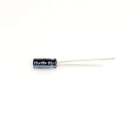
Aluminum Electrolytic Capacitors:
- Aluminum electrolytic capacitors are used for bulk decoupling and energy storage in power supply circuits.
- They offer high capacitance values but have higher ESR and lower frequency response compared to ceramic and tantalum capacitors.
-
Electrolytic capacitors are polarized and have a larger physical size compared to other types.
-
Film Capacitors:
- Film capacitors, such as polyester and polypropylene types, offer low ESR and high stability.
- They are suitable for decoupling in audio and high-frequency applications.
- Film capacitors have larger physical sizes compared to ceramic capacitors for a given capacitance value.
The table below summarizes the characteristics of different types of decoupling capacitors:
| Capacitor Type | Capacitance Range | ESR | Frequency Response | Polarized |
|---|---|---|---|---|
| Ceramic | pF to μF | Low | High | No |
| Tantalum | μF to hundreds of μF | Medium | Medium | Yes |
| Electrolytic | μF to thousands of μF | High | Low | Yes |
| Film | pF to μF | Low | Medium to High | No |

Selecting Decoupling Capacitors
When selecting decoupling capacitors for a circuit, several factors need to be considered to ensure optimal performance. These include:
- Capacitance Value:
- The capacitance value should be chosen based on the frequency range of the noise to be filtered and the current requirements of the circuit components.
- Higher capacitance values provide better low-frequency decoupling but may have higher ESR and larger physical size.
-
Lower capacitance values are suitable for high-frequency decoupling and can be placed closer to the components.
-
Voltage Rating:
- The voltage rating of the decoupling capacitor should be equal to or higher than the maximum expected voltage in the circuit.
-
Choosing a capacitor with a higher voltage rating provides a safety margin and helps prevent capacitor failure due to voltage stress.
-
ESR and ESL:
- Low equivalent series resistance (ESR) and low equivalent series inductance (ESL) are desirable for effective decoupling.
- Lower ESR allows for faster current delivery and reduces voltage ripple, while lower ESL improves high-frequency performance.
-
Ceramic capacitors generally have lower ESR and ESL compared to other types.
-
Temperature Coefficient:
- The temperature coefficient of the capacitor should be considered, especially in applications with a wide operating temperature range.
-
Capacitors with stable temperature coefficients, such as NP0 (C0G) ceramics, maintain their capacitance value over temperature variations.
-
Package Size and Mounting:
- The physical size and package of the decoupling capacitor should be compatible with the available board space and mounting requirements.
- Surface-mount packages, such as 0402, 0603, and 0805, are commonly used for decoupling capacitors due to their small size and low inductance.

Decoupling Capacitor Placement and Layout
Proper placement and layout of decoupling capacitors are critical for their effectiveness in reducing noise and maintaining signal integrity. Here are some guidelines for optimal decoupling capacitor placement and layout:
- Place capacitors close to the power pins:
- Decoupling capacitors should be placed as close as possible to the power pins of the ICs or components they are decoupling.
-
Minimizing the distance between the capacitor and the power pin reduces the inductance and resistance of the connecting traces, improving the high-frequency performance.
-
Use short and wide traces:
- The traces connecting the decoupling capacitor to the power pin and ground should be as short and wide as possible.
- Wider traces have lower resistance and inductance, allowing for better current flow and reduced voltage drop.
-
Avoid long and thin traces, as they introduce unwanted inductance and degrade the decoupling performance.
-
Minimize loop area:
- The loop area formed by the decoupling capacitor, power pin, and ground should be minimized to reduce inductance.
- Place the capacitor and ground connection on the same layer, directly underneath or adjacent to the power pin.
-
Avoid routing the power and ground traces on different layers, as it increases the loop area and inductance.
-
Use ground planes:
- Incorporate solid ground planes in the PCB design to provide a low-impedance return path for the decoupling capacitors.
- Ground planes help distribute the high-frequency currents and minimize inductance.
-
Connect the decoupling capacitors directly to the ground plane using vias or short traces.
-
Consider multi-layer ceramic capacitors:
- Multi-layer ceramic capacitors (MLCCs) offer low ESR and ESL, making them ideal for high-frequency decoupling.
- MLCCs can be stacked or placed in parallel to increase the effective capacitance and reduce the ESR.
-
When using multiple MLCCs, ensure that the spacing between them is sufficient to avoid mutual coupling and resonance effects.
-
Use a hierarchical decoupling scheme:
- Implement a hierarchical decoupling scheme with different capacitor values and types to address noise at various frequencies.
- Place larger bulk capacitors near the power entry point to the board for low-frequency decoupling and overall stability.
-
Use smaller decoupling capacitors, such as MLCCs, close to each IC or group of components for high-frequency decoupling.
-
Simulate and verify the design:
- Perform simulations and analysis of the decoupling network to optimize the capacitor values and placement.
- Use tools like power integrity simulators or electromagnetic field solvers to assess the effectiveness of the decoupling scheme.
- Verify the decoupling performance through measurements and testing to ensure the desired noise reduction and signal integrity.

FAQ
- What is the purpose of a decoupling capacitor?
-
A decoupling capacitor is used to reduce noise and stabilize the power supply voltage in electronic circuits. It decouples or isolates the high-frequency noise from the power supply, preventing it from interfering with the proper functioning of the circuit components.
-
What are the different types of decoupling capacitors?
-
The common types of decoupling capacitors include ceramic capacitors, tantalum capacitors, aluminum electrolytic capacitors, and film capacitors. Each type has its own characteristics and advantages, such as capacitance range, ESR, frequency response, and polarization.
-
How do I select the appropriate capacitance value for a decoupling capacitor?
-
The capacitance value should be chosen based on the frequency range of the noise to be filtered and the current requirements of the circuit components. Higher capacitance values provide better low-frequency decoupling, while lower capacitance values are suitable for high-frequency decoupling.
-
What is the importance of placing decoupling capacitors close to the power pins?
-
Placing decoupling capacitors close to the power pins of the components they are decoupling minimizes the inductance and resistance of the connecting traces. This allows for faster current delivery, better high-frequency performance, and effective noise suppression.
-
How does a hierarchical decoupling scheme work?
- A hierarchical decoupling scheme involves using different capacitor values and types to address noise at various frequencies. Larger bulk capacitors are placed near the power entry point to the board for low-frequency decoupling and overall stability, while smaller decoupling capacitors, such as MLCCs, are placed close to each IC or group of components for high-frequency decoupling.


Leave a Reply