What are Circuit Board Headers?
Circuit board headers, also known as pin headers or header connectors, are small, rectangular connectors that are mounted on a printed circuit board (PCB). They consist of a series of male pins arranged in a single row or multiple rows, which can be connected to female sockets or jumper wires. Headers provide a convenient way to establish temporary or permanent electrical connections, allowing for easy assembly, disassembly, and reconfiguration of electronic components.
Types of Circuit Board Headers
There are several types of circuit board headers available, each with its own characteristics and applications:
-
Single Row Headers: These headers have a single row of male pins, typically spaced at 0.1″ (2.54mm) intervals. They are commonly used for simple connections, such as power supply, low-speed signals, or programming interfaces.
-
Double Row Headers: Also known as dual row headers, these connectors have two parallel rows of male pins. They offer higher pin density and are often used for more complex connections, such as data buses or multi-signal interfaces.
-
Shrouded Headers: These headers feature a plastic shroud surrounding the pins, which helps guide the mating connector and prevent accidental misalignment. Shrouded headers are commonly used in applications where proper orientation and secure connection are critical.
-
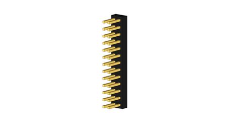
Right-Angle Headers: Unlike straight headers, right-angle headers have pins that are bent at a 90-degree angle. This allows for connections to be made parallel to the PCB surface, which can be useful in space-constrained designs or when connecting to ribbon cables.
-
Surface Mount Headers: These headers are designed for surface mount technology (SMT) assembly, where the pins are soldered directly onto the PCB surface without through-holes. Surface mount headers offer a lower profile and improved mechanical stability compared to through-hole headers.
Header Pin Counts and Pitches
Circuit board headers come in various pin counts and pitches to accommodate different design requirements:
| Pin Count | Typical Applications |
|---|---|
| 2-10 | Power supply, simple signals, programming |
| 11-20 | Data buses, multi-signal interfaces |
| 21-40 | Complex interfaces, high-density connections |
| 41+ | Specialized applications, custom designs |
The most common pin pitch for circuit board headers is 0.1″ (2.54mm), which provides a balance between compactness and ease of use. However, smaller pitches such as 0.05″ (1.27mm) or 0.079″ (2.00mm) are also available for high-density applications.
Applications of Circuit Board Headers
Circuit board headers find use in a wide range of electronic applications, from consumer devices to industrial equipment. Some common applications include:
-
Microcontroller Development Boards: Headers are extensively used in development boards like Arduino or Raspberry Pi to provide access to input/output pins, power supply, and communication interfaces.
-
Modular Electronics: Headers enable modular design approaches, where different functional blocks can be easily connected or swapped out as needed. This is particularly useful in prototyping, testing, and customization of electronic systems.
-
Expansion Boards: Circuit board headers are used to connect expansion boards or shields to the main PCB, allowing for additional functionality or capabilities to be added to a system.
-
Cable Assemblies: Headers can be used in conjunction with jumper wires or ribbon cables to create custom cable assemblies for interconnecting different parts of an electronic system.
-
Programming and Debugging: Headers provide convenient access points for programming and debugging interfaces, such as JTAG or SWD, enabling easy firmware updates and system diagnostics.

Selecting the Right Circuit Board Header
When choosing a circuit board header for your application, consider the following factors:
Pin Count and Pitch
Determine the number of pins required for your application and select a header with the appropriate pin count. Consider the available PCB space and the pitch of the mating connector or cable.
Mounting Type
Decide whether through-hole or surface mount headers are more suitable for your PCB Assembly process and design constraints. Through-hole headers offer better mechanical stability and are easier to hand-solder, while surface mount headers provide a lower profile and are better suited for automated assembly.
Current Rating
Ensure that the header’s current rating is sufficient for your application’s power requirements. Typical current ratings for circuit board headers range from 1A to 3A per pin, depending on the pin size and material.
Operating Environment
Consider the environmental conditions in which the header will be used, such as temperature range, humidity, and vibration. Select headers with appropriate materials and plating options to ensure reliable operation in your specific environment.
Mating Connector Compatibility
Verify that the selected header is compatible with the intended mating connector or cable. Consider factors such as pin spacing, orientation, and keying features to ensure proper alignment and connection.

Best Practices for Using Circuit Board Headers
To ensure reliable and efficient use of circuit board headers, follow these best practices:
-
Proper PCB Layout: Design your PCB layout with appropriate pad sizes, spacing, and hole diameters for the selected header. Follow the manufacturer’s recommendations for footprint and soldering guidelines.
-
Mechanical Support: For headers with a large number of pins or those subjected to frequent mating cycles, consider adding mechanical support, such as mounting holes or reinforced PCB areas, to prevent stress on the solder joints.
-
Keying and Orientation: Use headers with keying features or asymmetric pin arrangements to prevent incorrect mating or reversed polarity connections. Clearly mark the orientation of the header on the PCB Silkscreen.
-
Strain Relief: When using headers with cable assemblies, provide adequate strain relief to prevent excessive stress on the pins and solder joints. Use cable ties, adhesive anchors, or connector housings to secure the cables.
-
Soldering Techniques: Follow proper soldering techniques when attaching headers to the PCB. Use appropriate soldering temperature, time, and Solder volume to create reliable solder joints. Inspect the solder joints for any defects or bridging.

Frequently Asked Questions (FAQ)
1. Can I mix and match different types of circuit board headers in my design?
Yes, you can use different types of headers in your design, depending on the specific requirements of each connection. However, ensure that the selected headers are compatible with the mating connectors and that the overall design is consistent and easy to assemble.
2. Are circuit board headers polarized?
Some circuit board headers are polarized, meaning they have a specific orientation that prevents incorrect mating. This is typically achieved through keying features, such as a missing pin or a slot in the plastic housing. Non-polarized headers can be mated in either orientation.
3. How do I determine the current rating of a circuit board header?
The current rating of a header depends on factors such as pin size, material, and plating. Consult the manufacturer’s datasheet for the specific header you are using to find its rated current capacity. As a general rule, larger pin diameters and higher-quality materials will have higher current ratings.
4. Can I replace a damaged pin on a circuit board header?
Replacing a single damaged pin on a header is possible but can be challenging. It involves carefully desoldering the damaged pin, removing it from the plastic housing, and soldering a new pin in its place. However, this process can be time-consuming and may risk damaging the surrounding pins or the PCB. In most cases, it is more practical to replace the entire header.
5. How do I prevent accidental disconnection of jumper wires from a header?
To prevent accidental disconnection of jumper wires, you can use headers with locking mechanisms, such as friction locks or latches. Alternatively, you can use cable ties or adhesive anchors to secure the wires to the PCB or nearby components. Proper strain relief and routing of the wires can also help minimize the risk of accidental disconnection.
Conclusion
Circuit board headers are essential components in electronic design, providing a reliable and flexible way to establish electrical connections between different parts of a system. By understanding the types, applications, and key considerations of circuit board headers, designers can select the most appropriate headers for their projects and ensure optimal performance and reliability. Following best practices for PCB layout, mechanical support, and soldering techniques will help create robust and efficient electronic assemblies using circuit board headers.


Leave a Reply