What are PCB Tolerances?
PCB tolerances refer to the acceptable range of variations in the physical dimensions and properties of a PCB. These tolerances are essential to ensure that the PCB functions as intended and fits properly with other components in an Electronic Assembly. PCB Manufacturers strive to maintain tight tolerances to guarantee the quality and reliability of their products.
Types of PCB Tolerances
There are several types of tolerances that are critical in PCB manufacturing:
-
Dimensional Tolerances: These tolerances relate to the physical dimensions of the PCB, such as length, width, and thickness. They also encompass the size and location of holes, pads, and other features on the board.
-
Electrical Tolerances: Electrical tolerances pertain to the electrical properties of the PCB, such as impedance, capacitance, and resistance. These tolerances are crucial for maintaining signal integrity and preventing issues like crosstalk and signal reflections.
-
Material Tolerances: Material tolerances relate to the properties of the materials used in PCB Fabrication, such as the dielectric constant and loss tangent of the substrate, and the conductivity of the copper traces.
-
Manufacturing Tolerances: These tolerances encompass the variations that can occur during the PCB manufacturing process, such as the accuracy of copper etching, the registration of layers, and the alignment of drill holes.
Factors Influencing PCB Tolerances
Several factors can impact the tolerances achievable in PCB manufacturing:
-
Material Selection: The choice of substrate material, copper weight, and solder mask can affect the dimensional stability and electrical properties of the PCB.
-
Manufacturing Process: Different PCB manufacturing processes, such as subtractive etching, additive manufacturing, and semi-additive processing, have varying levels of precision and tolerance control.
-
Board Complexity: The complexity of the PCB design, including the number of layers, the density of components, and the presence of fine-pitch features, can make it more challenging to maintain tight tolerances.
-
Environmental Factors: Temperature, humidity, and other environmental conditions can cause materials to expand or contract, affecting the dimensional stability of the PCB.
Dimensional Tolerances in PCB Manufacturing
Dimensional tolerances are perhaps the most critical aspect of PCB manufacturing, as they directly impact the fit and function of the board in the final assembly. Let’s take a closer look at some of the key dimensional tolerances in PCB fabrication.
Board Thickness Tolerance
The thickness of a PCB is determined by the number of layers and the thickness of the substrate material. The tolerance on board thickness is typically specified as a plus-or-minus deviation from the nominal value. For example, a 1.6mm thick board might have a thickness tolerance of ±0.1mm.
| Number of Layers | Nominal Thickness (mm) | Tolerance (mm) |
|---|---|---|
| 1 – 2 | 0.8 | ±0.1 |
| 4 | 1.6 | ±0.15 |
| 6 – 8 | 2.4 | ±0.2 |
| 10 – 12 | 3.2 | ±0.3 |
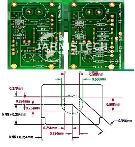
Hole Size and Position Tolerance
The size and position of holes on a PCB are critical for component placement and solderability. The hole size tolerance is usually expressed as a plus-or-minus deviation from the nominal diameter, while the position tolerance is given as a plus-or-minus deviation from the true position.
| Hole Type | Nominal Size (mm) | Size Tolerance (mm) | Position Tolerance (mm) |
|---|---|---|---|
| Standard | 0.8 – 6.0 | ±0.1 | ±0.15 |
| Micro Via | 0.1 – 0.3 | ±0.05 | ±0.05 |
| Via | 0.4 – 0.7 | ±0.08 | ±0.1 |
Copper Trace Width and Spacing Tolerance
The width and spacing of copper traces on a PCB determine its electrical characteristics and current-carrying capacity. The tolerance on trace width and spacing is typically expressed as a minimum and maximum deviation from the nominal value.
| Trace Parameter | Nominal Value (mm) | Minimum (mm) | Maximum (mm) |
|---|---|---|---|
| Width | 0.1 – 0.5 | -0.02 | +0.02 |
| Spacing | 0.1 – 0.5 | -0.02 | +0.02 |

Electrical Tolerances in PCB Manufacturing
Electrical tolerances are essential for ensuring the proper functioning and signal integrity of a PCB. These tolerances pertain to the electrical properties of the board, such as impedance, capacitance, and resistance.
Impedance Tolerance
Impedance control is critical in high-speed PCB designs to maintain signal integrity and prevent reflections. The tolerance on impedance is usually specified as a percentage deviation from the target value.
| Impedance Type | Target Value (Ω) | Tolerance (%) |
|---|---|---|
| Single-ended | 50 – 75 | ±10 |
| Differential | 90 – 120 | ±10 |
Capacitance and Resistance Tolerance
The capacitance and resistance of a PCB can affect its electrical performance, particularly at high frequencies. The tolerance on capacitance and resistance is typically expressed as a percentage deviation from the nominal value.
| Parameter | Nominal Value | Tolerance (%) |
|---|---|---|
| Capacitance | 1 – 100 pF | ±10 |
| Resistance | 0.1 – 10 Ω | ±10 |

Material Tolerances in PCB Manufacturing
The choice of materials used in PCB fabrication can significantly impact the performance and reliability of the final product. Material tolerances relate to the properties of these materials, such as the dielectric constant and loss tangent of the substrate, and the conductivity of the copper traces.
Substrate Material Tolerance
The dielectric constant (Dk) and loss tangent (Df) of the substrate material determine the electrical behavior of the PCB. The tolerance on these properties is usually specified as a percentage deviation from the nominal value.
| Substrate Material | Nominal Dk | Dk Tolerance (%) | Nominal Df | Df Tolerance (%) |
|---|---|---|---|---|
| FR-4 | 4.2 – 4.5 | ±2 | 0.02 | ±10 |
| Rogers RO4003C | 3.38 | ±0.05 | 0.0027 | ±10 |
| Isola IS410 | 3.96 | ±0.04 | 0.0127 | ±10 |
Copper Conductivity Tolerance
The conductivity of the copper traces on a PCB affects its electrical resistance and current-carrying capacity. The tolerance on copper conductivity is typically expressed as a percentage of the International Annealed Copper Standard (IACS).
| Copper Type | Nominal Conductivity (%IACS) | Tolerance (%IACS) |
|---|---|---|
| Standard | 100 | ±5 |
| High-Temp | 97 | ±5 |

Manufacturing Tolerances in PCB Fabrication
Manufacturing tolerances encompass the variations that can occur during the PCB fabrication process, such as the accuracy of copper etching, the registration of layers, and the alignment of drill holes.
Etching Tolerance
Etching is the process of removing unwanted copper from the PCB to create the desired circuit pattern. The tolerance on etching is usually specified as a minimum and maximum deviation from the nominal trace width and spacing.
| Etching Parameter | Nominal Value (mm) | Minimum (mm) | Maximum (mm) |
|---|---|---|---|
| Trace Width | 0.1 – 0.5 | -0.02 | +0.02 |
| Trace Spacing | 0.1 – 0.5 | -0.02 | +0.02 |
Layer Registration Tolerance
In Multi-layer PCBs, the alignment of layers is critical for ensuring proper connectivity and preventing short circuits. The tolerance on layer registration is typically expressed as a maximum deviation from the true position.
| Number of Layers | Registration Tolerance (mm) |
|---|---|
| 2 – 4 | ±0.1 |
| 6 – 8 | ±0.15 |
| 10 – 12 | ±0.2 |
Drill Hole Alignment Tolerance
The alignment of drill holes in a PCB is essential for component placement and solderability. The tolerance on drill hole alignment is usually specified as a maximum deviation from the true position.
| Hole Type | Alignment Tolerance (mm) |
|---|---|
| Standard | ±0.1 |
| Micro Via | ±0.05 |
| Via | ±0.08 |
Frequently Asked Questions (FAQ)
-
What are the most common tolerances specified for PCBs?
The most common tolerances specified for PCBs include dimensional tolerances (board thickness, hole size and position), electrical tolerances (impedance, capacitance, resistance), and manufacturing tolerances (etching, layer registration, drill hole alignment). -
How do PCB tolerances affect the performance and reliability of the board?
PCB tolerances directly impact the performance and reliability of the board by ensuring proper fit, connectivity, and signal integrity. Tight tolerances help prevent issues such as signal reflections, crosstalk, and short circuits. -
What factors influence the achievable tolerances in PCB manufacturing?
The achievable tolerances in PCB manufacturing are influenced by several factors, including material selection, manufacturing process, board complexity, and environmental conditions. -
How can designers ensure that their PCB meets the required tolerances?
Designers can ensure that their PCB meets the required tolerances by carefully selecting materials, specifying appropriate tolerances on the design, and communicating closely with the PCB manufacturer throughout the fabrication process. -
What are the consequences of not maintaining proper PCB tolerances?
Failure to maintain proper PCB tolerances can lead to a variety of issues, such as poor component fit, signal integrity problems, reduced reliability, and even complete failure of the electronic assembly.
In conclusion, PCB tolerances play a vital role in ensuring the performance, reliability, and overall quality of printed circuit boards. By understanding the types of tolerances, the factors that influence them, and the importance of maintaining tight tolerances throughout the manufacturing process, designers and manufacturers can work together to create high-quality PCBs that meet the demands of modern electronic applications.


Leave a Reply