Understanding PCB Drill Sizes
What are PCB Drill Sizes?
PCB drill sizes refer to the diameter of the holes drilled into a printed circuit board (PCB) to accommodate various components, such as through-hole components, vias, and mounting holes. These drill sizes are essential for ensuring proper fitment and electrical connectivity within the PCB.
Importance of Accurate PCB Drill Sizes
Accurate PCB drill sizes are crucial for several reasons:
-
Component compatibility: Correct drill sizes ensure that through-hole components fit properly into the designated holes, allowing for secure mounting and reliable electrical connections.
-
Via functionality: Vias, which are small holes that connect different layers of a multi-layer PCB, require precise drill sizes to maintain proper electrical conductivity and signal integrity.
-
Manufacturing efficiency: Using standard drill sizes helps optimize the manufacturing process, reducing the need for custom tooling and minimizing production costs.
-
Reliability: Accurately drilled holes contribute to the overall reliability and longevity of the PCB, as they prevent issues such as component misalignment, poor electrical connections, and mechanical stress.
Standard PCB Drill Sizes
Imperial vs. Metric Measurements
PCB drill sizes can be expressed in both imperial (inches) and metric (millimeters) units. While imperial measurements are more common in the United States, metric measurements are widely used in other parts of the world. It’s essential to use the appropriate units when specifying drill sizes to avoid confusion and ensure compatibility with manufacturing processes.
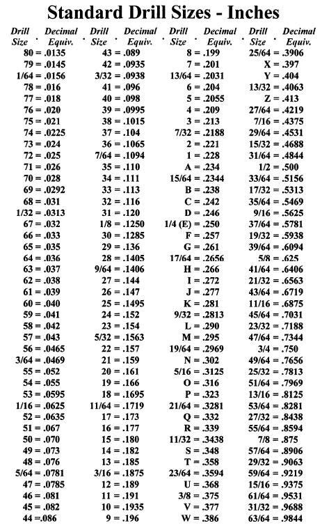
Common PCB Drill Sizes
The following table lists some of the most common PCB drill sizes in both imperial and metric units:
| Drill Number | Inch | Metric (mm) |
|---|---|---|
| 80 | 0.0135 | 0.343 |
| 79 | 0.0145 | 0.368 |
| 78 | 0.016 | 0.406 |
| 77 | 0.018 | 0.457 |
| 76 | 0.020 | 0.508 |
| 75 | 0.021 | 0.533 |
| 74 | 0.0225 | 0.572 |
| 73 | 0.024 | 0.610 |
| 72 | 0.025 | 0.635 |
| 71 | 0.026 | 0.660 |
| 70 | 0.028 | 0.711 |
| 69 | 0.0292 | 0.742 |
| 68 | 0.031 | 0.787 |
| 67 | 0.032 | 0.813 |
| 66 | 0.033 | 0.838 |
| 65 | 0.035 | 0.889 |
| 64 | 0.036 | 0.914 |
| 63 | 0.037 | 0.940 |
| 62 | 0.038 | 0.965 |
| 61 | 0.039 | 0.991 |
| 60 | 0.040 | 1.016 |
These drill sizes cover a wide range of applications, from small vias to larger mounting holes for components such as connectors and switches.
Selecting the Appropriate Drill Size
When choosing the appropriate drill size for a specific component or application, consider the following factors:
-
Component lead diameter: Ensure that the drill size is slightly larger than the lead diameter of the through-hole component to allow for easy insertion and a secure fit.
-
Pad size: The drill size should be smaller than the pad size to maintain adequate annular ring (the conductive area around the hole) for reliable electrical connections.
-
PCB Thickness: Thicker PCBs may require larger drill sizes to accommodate longer component leads and maintain hole quality.
-
Manufacturing capabilities: Consult with your PCB manufacturer to understand their available drill sizes and any limitations or recommendations based on their equipment and processes.

Advanced Topics in PCB Drill Sizes
Aspect Ratio
Aspect ratio is the relationship between the depth of a drilled hole and its diameter. In PCB manufacturing, the aspect ratio is an essential consideration, as it affects the manufacturability and reliability of the board.
A higher aspect ratio (deeper hole relative to its diameter) can present challenges in maintaining hole quality, such as ensuring even copper plating throughout the hole. Generally, an aspect ratio of 8:1 or less is considered manufacturable, while higher aspect ratios may require specialized drilling techniques or additional processing steps.
When designing a PCB, it’s crucial to consider the aspect ratio and work with your manufacturer to determine the feasible drill sizes and PCB thicknesses for your specific application.
Plated vs. Non-Plated Holes
PCB holes can be categorized as plated or non-plated, depending on their intended function and the manufacturing process.
Plated holes, also known as plated through-holes (PTH), are drilled and then electroplated with a conductive material, typically copper, to create an electrical connection between the layers of the PCB. Plated holes are commonly used for mounting through-hole components and creating vias.
Non-plated holes, or NPTHs, are drilled but not plated with a conductive material. These holes are used for mechanical purposes, such as mounting the PCB to an enclosure or accommodating non-electrical components like standoffs or heat sinks.
When specifying drill sizes for your PCB, it’s essential to differentiate between plated and non-plated holes, as they may have different size requirements and tolerances based on their intended function.
Drill Size Tolerances
PCB drill size tolerances refer to the acceptable range of variation in the diameter of a drilled hole. These tolerances are necessary to account for manufacturing variability and ensure that the holes meet the required specifications for component fitment and electrical connectivity.
Drill size tolerances are typically expressed as a plus/minus value, such as ±0.003″ or ±0.076mm, depending on the unit of measurement. Tighter tolerances may be required for high-precision applications or when working with smaller components, while larger tolerances may be acceptable for less critical holes or larger components.
It’s important to discuss drill size tolerances with your PCB manufacturer to ensure that they can meet your requirements and to understand any potential impact on manufacturing costs or lead times.

Frequently Asked Questions (FAQ)
- What is the most common drill size for through-hole components?
-
The most common drill size for through-hole components is typically 0.8mm or 1.0mm, which corresponds to drill sizes 65 and 60, respectively, in the imperial system. However, the specific drill size required may vary depending on the component and the application.
-
Can I use any drill size for my PCB?
-
While there is a wide range of standard drill sizes available, not all PCB manufacturers can accommodate every size. It’s essential to consult with your manufacturer to understand their capabilities and recommendations based on your specific design requirements.
-
What happens if I specify an incorrect drill size?
-
Specifying an incorrect drill size can lead to various issues, such as difficulty in assembling components, poor electrical connections, and even component damage. Always double-check your drill size specifications and verify them with your manufacturer to avoid costly mistakes.
-
How do I determine the appropriate drill size for a specific component?
-
To determine the appropriate drill size for a specific component, refer to the component’s datasheet or consult with the component manufacturer. They will provide information on the recommended hole diameter and any additional requirements, such as pad size and spacing.
-
Can I use different drill sizes on the same PCB?
- Yes, it’s common to use different drill sizes on the same PCB to accommodate various components and functions. However, it’s essential to minimize the number of unique drill sizes to optimize the manufacturing process and reduce costs. Work with your manufacturer to strike a balance between design requirements and manufacturing efficiency.

Conclusion
Understanding PCB drill sizes is crucial for designing and manufacturing reliable and cost-effective printed circuit boards. By selecting the appropriate drill sizes, considering aspect ratios, and working closely with your PCB manufacturer, you can ensure that your PCB meets the required specifications and performs as intended.
As PCB technology continues to advance, with increasingly smaller components and higher-density designs, the importance of accurate and well-specified drill sizes will only continue to grow. By staying informed about the latest developments in PCB manufacturing and collaborating with experienced professionals, you can navigate the complexities of PCB drill sizes and create successful, high-quality PCBs for your applications.


Leave a Reply