Introduction to PCB Electrical Testing
Printed Circuit Boards (PCBs) are the backbone of modern electronics, connecting various components to create functional devices. To ensure the reliability and performance of these PCBs, it is essential to conduct thorough electrical testing. PCB electrical testing involves a series of processes that verify the integrity of the board’s connections, components, and overall functionality. In this comprehensive article, we will delve into the world of PCB electrical testing, exploring its importance, techniques, and best practices.
The Importance of PCB Electrical Testing
Ensuring Reliability and Functionality
PCB electrical testing is crucial for ensuring the reliability and functionality of electronic devices. By conducting rigorous tests, manufacturers can identify and rectify any issues before the PCBs are integrated into the final product. This proactive approach helps prevent potential failures and malfunctions, ultimately saving time and resources in the long run.
Detecting Manufacturing Defects
During the PCB manufacturing process, various defects can occur, such as short circuits, open circuits, and component misalignments. Electrical testing helps detect these defects early in the production cycle, allowing for timely corrections and reducing the risk of defective products reaching the market.
Meeting Industry Standards and Regulations
Many industries, such as automotive, aerospace, and medical, have strict standards and regulations governing the quality and safety of electronic devices. PCB electrical testing ensures that the boards meet these stringent requirements, guaranteeing the reliability and performance expected in critical applications.

Types of PCB Electrical Tests
Continuity Testing
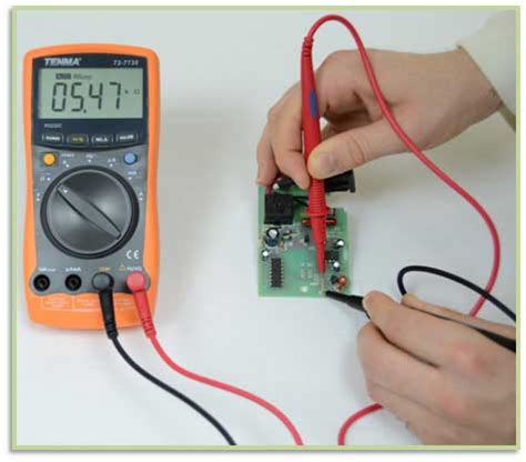
Continuity testing is a fundamental PCB electrical test that verifies the integrity of the connections between components. It checks for open circuits, ensuring that current can flow through the intended paths without interruption. Continuity testing is typically performed using a multimeter or a dedicated continuity tester.
Resistance Testing
Resistance testing measures the opposition to current flow in a circuit. It helps identify any discrepancies in the resistance values of components, such as resistors, and ensures that they fall within the specified tolerance range. Resistance testing is essential for verifying the accuracy of the PCB’s electrical characteristics.
Insulation Resistance Testing
Insulation resistance testing measures the resistance between isolated conductors, such as adjacent traces or layers, to ensure that there are no unintended leakage paths. This test helps detect potential short circuits or insulation breakdowns that could compromise the PCB’s performance and safety.
Capacitance Testing
Capacitance testing measures the ability of a component, such as a capacitor, to store an electrical charge. It verifies that the capacitance values are within the specified range and helps identify any defective or out-of-tolerance components. Capacitance testing is particularly important for PCBs that rely on precise timing or filtering.
Dielectric Withstand Testing
Dielectric withstand testing, also known as HiPot Testing, applies a high voltage between isolated conductors to ensure that the insulation can withstand the specified voltage without breakdown. This test helps verify the integrity of the PCB’s insulation and prevents potential safety hazards.
Functional Testing
Functional testing involves powering up the PCB and verifying its overall functionality. It checks whether the board performs as intended, with all components and subsystems working together seamlessly. Functional testing often includes testing the PCB’s inputs, outputs, and any specific features or functions.

PCB Electrical Testing Techniques
Flying Probe Testing
Flying probe testing is an automated technique that uses movable probes to make contact with specific points on the PCB. The probes can move quickly and accurately, allowing for efficient testing of complex boards. Flying probe testing is particularly useful for low-volume production or prototypes, as it eliminates the need for dedicated test fixtures.
In-Circuit Testing (ICT)
In-circuit testing involves using a bed-of-nails fixture to make contact with the PCB’s test points. The fixture contains a grid of spring-loaded pins that press against the test points, allowing for simultaneous testing of multiple points. ICT is well-suited for high-volume production and provides comprehensive coverage of the PCB’s components and connections.
Boundary Scan Testing
Boundary scan testing, also known as JTAG testing, is a technique that uses a serial interface to access and test the PCB’s digital components. It allows for testing of the interconnections between components without the need for physical access to each pin. Boundary scan testing is particularly useful for testing high-density boards with limited test points.
Automated Optical Inspection (AOI)
Although not strictly an electrical test, automated optical inspection (AOI) is often used in conjunction with electrical testing to verify the PCB’s physical characteristics. AOI uses high-resolution cameras and image processing algorithms to detect any visual defects, such as solder bridges, missing components, or incorrect component placements.

Best Practices for PCB Electrical Testing
Developing a Comprehensive Test Plan
To ensure thorough and efficient PCB electrical testing, it is essential to develop a comprehensive test plan. The test plan should outline the specific tests to be performed, the test sequence, and the acceptance criteria. It should also consider the PCB’s design, components, and intended application to determine the most appropriate testing techniques.
Designing for Testability
Designing PCBs with testability in mind can greatly simplify the electrical testing process. This involves incorporating test points, boundary scan chains, and other features that facilitate testing. By considering testability during the design phase, manufacturers can reduce testing time, improve test coverage, and minimize the risk of undetected defects.
Establishing Test Fixtures and Jigs
Test fixtures and jigs play a crucial role in PCB electrical testing, particularly for in-circuit testing and functional testing. These custom-designed tools ensure accurate and repeatable contact with the PCB’s test points, enabling efficient and reliable testing. Proper design and maintenance of test fixtures and jigs are essential for consistent and accurate test results.
Implementing Automated Testing
Automated testing systems can significantly enhance the efficiency and accuracy of PCB electrical testing. These systems integrate various testing techniques, such as flying probe testing, in-circuit testing, and boundary scan testing, into a streamlined process. Automated testing reduces human error, increases throughput, and provides consistent and repeatable results.
Documenting and Analyzing Test Results
Documenting and analyzing test results is crucial for identifying trends, improving processes, and ensuring the quality of PCBs. Test data should be systematically recorded, including details such as the test parameters, results, and any observed anomalies. Regular analysis of test data can help identify recurring issues, optimize testing procedures, and drive continuous improvement efforts.
Frequently Asked Questions (FAQ)
-
Q: What is the purpose of PCB electrical testing?
A: The purpose of PCB electrical testing is to verify the integrity, functionality, and reliability of printed circuit boards. It helps identify manufacturing defects, ensures compliance with industry standards, and prevents potential failures in the final product. -
Q: What are the common types of PCB electrical tests?
A: Common types of PCB electrical tests include continuity testing, resistance testing, insulation resistance testing, capacitance testing, dielectric withstand testing, and functional testing. Each test focuses on specific aspects of the PCB’s electrical characteristics and performance. -
Q: What is the difference between flying probe testing and in-circuit testing?
A: Flying probe testing uses movable probes to make contact with specific points on the PCB, while in-circuit testing uses a bed-of-nails fixture with fixed pins. Flying probe testing is more flexible and suitable for low-volume production, while in-circuit testing is faster and better suited for high-volume production. -
Q: Why is designing for testability important in PCB manufacturing?
A: Designing for testability simplifies the electrical testing process by incorporating features such as test points and boundary scan chains. It reduces testing time, improves test coverage, and minimizes the risk of undetected defects, ultimately leading to higher quality PCBs. -
Q: How can automated testing improve PCB electrical testing?
A: Automated testing systems integrate various testing techniques into a streamlined process, reducing human error and increasing throughput. They provide consistent and repeatable results, enabling faster and more accurate testing of PCBs. Automated testing also allows for easy documentation and analysis of test data.
Conclusion
PCB electrical testing is a critical aspect of ensuring the reliability, functionality, and safety of electronic devices. By conducting thorough tests, manufacturers can identify and rectify defects, meet industry standards, and deliver high-quality products to their customers. Understanding the various types of electrical tests, techniques, and best practices is essential for implementing an effective testing strategy.
From continuity and resistance testing to advanced techniques like flying probe and boundary scan testing, PCB electrical testing offers a comprehensive approach to verifying the integrity of the board’s connections and components. By designing for testability, establishing robust test fixtures, and leveraging automated testing systems, manufacturers can streamline their testing processes and achieve consistent and accurate results.
As the electronics industry continues to evolve, with increasing complexity and miniaturization of PCBs, the importance of electrical testing will only grow. By staying updated with the latest testing technologies and best practices, manufacturers can ensure the reliability and performance of their products in an increasingly competitive market.
References
- IPC-9252A, “Requirements for Electrical Testing of Unpopulated Printed Boards”
- IPC-TM-650, “Test Methods Manual”
- IPC-A-610, “Acceptability of Electronic Assemblies”


Leave a Reply