What is a Rigid-Flex PCB?
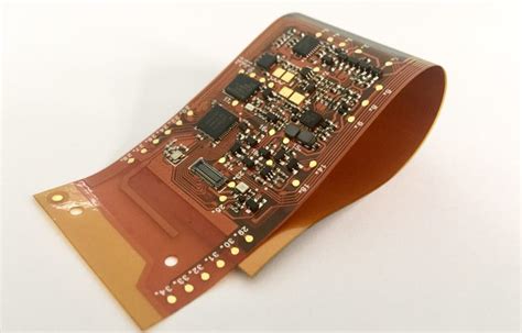
A Rigid-Flex PCB, also known as a Rigid-Flex Circuit, is a unique type of printed circuit board that combines the benefits of both rigid and flexible PCBs. It consists of multiple layers of flexible PCB substrates, such as polyimide, that are laminated together with traditional rigid PCB materials, like FR-4. This hybrid design allows for the creation of complex, three-dimensional circuit structures that can be folded, bent, or twisted to fit into confined spaces or to connect multiple rigid PCB sections.
Advantages of Rigid-Flex PCBs
Rigid-Flex PCBs offer several advantages over traditional rigid PCBs:
- Space Savings: By allowing the PCB to fold and conform to the available space, Rigid-Flex PCBs enable more compact device designs.
- Reduced Weight: The use of flexible materials and the elimination of connectors and cables contribute to overall weight reduction.
- Increased Reliability: With fewer interconnects and connectors, Rigid-Flex PCBs minimize potential points of failure, enhancing reliability.
- Improved Signal Integrity: The shorter signal paths and reduced number of interconnects in Rigid-Flex PCBs lead to better signal integrity and reduced noise.
- Enhanced Flexibility: Rigid-Flex PCBs can be designed to bend, fold, or twist, accommodating unique device form factors and mechanical requirements.
Rigid-Flex PCB Construction
Layers and Materials
A Rigid-Flex PCB consists of several layers, each serving a specific purpose:
- Flexible Layers: These layers are made of thin, flexible substrates like polyimide. They allow the PCB to bend and flex as needed. The most common flexible substrate materials are:
- Polyimide (PI)
- Polyester (PET)
-
Flexible FR-4
-
Rigid Layers: These layers are made of standard rigid PCB materials, such as FR-4, and provide structural support and stability to the PCB.
-
Copper Layers: Copper foil is used for the conductive traces and pads on both the flexible and rigid layers. The thickness of the copper can vary depending on the electrical requirements of the circuit.
-
Adhesive Layers: Adhesive materials are used to bond the flexible and rigid layers together. These adhesives must be compatible with the PCB materials and able to withstand the stresses of flexing and bending.
Fabrication Process
The fabrication process for Rigid-Flex PCBs is more complex than that of standard rigid PCBs. It involves several key steps:
-
Layer Preparation: The flexible and rigid layers are prepared separately. This includes applying photoresist, exposing the circuit patterns, and etching the copper.
-
Lamination: The prepared layers are aligned and laminated together using heat and pressure. The adhesive layers bond the flexible and rigid sections.
-
Drilling and Plating: Holes are drilled through the laminated board, and the walls of the holes are plated with copper to create electrical connections between layers.
-
Cutting and Profiling: The laminated board is cut and profiled to the desired shape, including any cutouts or openings for components or mounting.
-
Surface Finishing: The exposed copper surfaces are finished with a protective coating, such as ENIG (Electroless Nickel Immersion Gold) or HASL (Hot Air Solder Leveling), to prevent oxidation and improve solderability.

Designing Rigid-Flex PCBs
Design Considerations
Designing Rigid-Flex PCBs requires careful consideration of several factors:
-
Bend Radius: The minimum bend radius of the flexible sections must be determined based on the thickness and material properties of the flexible layers. Exceeding the minimum bend radius can cause damage to the PCB.
-
Bend Locations: The placement of components and traces should be optimized to minimize stress on the flexible sections during bending. Bends should be located away from components and plated through-holes whenever possible.
-
Stiffener Placement: Stiffeners can be added to the flexible sections to provide additional support and prevent excessive bending. The placement and size of the stiffeners should be carefully considered to ensure proper flexibility and reliability.
-
Trace Routing: Traces on the flexible layers should be routed to minimize stress during bending. This can be achieved by using curved traces, avoiding sharp corners, and providing sufficient clearance between traces and the edge of the PCB.
-
Layer Stackup: The layer stackup should be designed to balance the electrical requirements of the circuit with the mechanical properties of the flexible and rigid materials. The number and thickness of the layers, as well as the placement of ground and power planes, should be carefully considered.
Design Tools and Software
Designing Rigid-Flex PCBs requires specialized CAD tools and software that can handle the unique requirements of flexible and rigid layers. Some popular PCB design software packages that support Rigid-Flex Design include:
- Altium Designer
- Cadence Allegro
- Mentor Graphics PADS
- Zuken CR-8000
These tools provide features such as 3D modeling, layer stackup management, and bend simulation to help designers create reliable and manufacturable Rigid-Flex PCBs.

Applications of Rigid-Flex PCBs
Rigid-Flex PCBs are used in a wide range of applications that require compact, lightweight, and reliable electronic packaging. Some common applications include:
-
Aerospace and Defense: Rigid-Flex PCBs are used in avionics, satellites, and military equipment where space is limited, and reliability is critical.
-
Medical Devices: Wearable medical devices, implantable sensors, and diagnostic equipment often utilize Rigid-Flex PCBs for their compact size and flexibility.
-
Consumer Electronics: Smartphones, smartwatches, and other portable devices use Rigid-Flex PCBs to achieve slim, compact designs with robust functionality.
-
Automotive: Rigid-Flex PCBs are used in advanced driver assistance systems (ADAS), infotainment systems, and other automotive electronics that require reliable operation in harsh environments.
-
Industrial Equipment: Rigid-Flex PCBs are used in industrial control systems, robotics, and automation equipment where space is limited, and reliability is essential.

Challenges and Limitations
While Rigid-Flex PCBs offer numerous benefits, there are also some challenges and limitations to consider:
-
Higher Cost: Rigid-Flex PCBs are typically more expensive than traditional rigid PCBs due to the complex fabrication process and specialized materials required.
-
Limited Flexibility: Although Rigid-Flex PCBs offer significant flexibility compared to rigid PCBs, there are still limitations on the bend radius and the number of flex cycles the board can withstand.
-
Design Complexity: Designing Rigid-Flex PCBs requires specialized knowledge and tools to ensure proper functionality and reliability. The complex nature of Rigid-Flex designs can lead to longer development times and increased design costs.
-
Manufacturing Challenges: The fabrication process for Rigid-Flex PCBs is more complex than that of standard rigid PCBs, requiring specialized equipment and expertise. This can limit the number of manufacturers capable of producing Rigid-Flex PCBs and may result in longer lead times.
Future Trends and Developments
As electronic devices continue to become smaller, more complex, and more interconnected, the demand for Rigid-Flex PCBs is expected to grow. Some future trends and developments in Rigid-Flex PCB technology include:
-
Advanced Materials: Researchers are exploring new materials, such as graphene and carbon nanotubes, that could offer improved electrical and mechanical properties for Rigid-Flex PCBs.
-
Increased Complexity: As design tools and manufacturing processes advance, Rigid-Flex PCBs are likely to become even more complex, with more layers, finer features, and more intricate bend profiles.
-
Internet of Things (IoT): The growth of the IoT is driving demand for compact, flexible, and reliable PCBs that can be integrated into a wide range of connected devices.
-
5G and High-Speed Applications: The deployment of 5G networks and the increasing demand for high-speed electronics will require Rigid-Flex PCBs that can support higher frequencies and faster data rates while maintaining signal integrity.
-
Sustainable Manufacturing: As environmental concerns grow, there will be a greater focus on developing eco-friendly materials and manufacturing processes for Rigid-Flex PCBs, such as halogen-free materials and low-VOC adhesives.
Frequently Asked Questions (FAQ)
-
Q: What is the difference between a Rigid-Flex PCB and a flexible PCB?
A: A Rigid-Flex PCB combines both rigid and Flexible PCB Materials, allowing for the creation of three-dimensional circuit structures that can be folded, bent, or twisted. A flexible PCB, on the other hand, is made entirely of flexible materials and does not include any rigid sections. -
Q: Can Rigid-Flex PCBs be repaired?
A: Repairing Rigid-Flex PCBs can be challenging due to their complex structure and the use of specialized materials. In most cases, it is more cost-effective to replace a damaged Rigid-Flex PCB rather than attempting to repair it. -
Q: How long do Rigid-Flex PCBs last?
A: The lifespan of a Rigid-Flex PCB depends on various factors, such as the materials used, the operating environment, and the number of flex cycles experienced. With proper design and manufacturing, Rigid-Flex PCBs can last for many years in demanding applications. -
Q: Are Rigid-Flex PCBs more expensive than traditional rigid PCBs?
A: Yes, Rigid-Flex PCBs are typically more expensive than traditional rigid PCBs due to the complex fabrication process, specialized materials, and additional design considerations required. -
Q: Can Rigid-Flex PCBs be manufactured in-house?
A: Manufacturing Rigid-Flex PCBs requires specialized equipment, materials, and expertise. While some large companies may have the capabilities to manufacture Rigid-Flex PCBs in-house, most businesses rely on specialized PCB fabrication houses to produce their Rigid-Flex designs.
Conclusion
Rigid-Flex PCBs offer a unique combination of flexibility and stability, enabling the creation of compact, lightweight, and reliable electronic devices. By understanding the construction, design considerations, and applications of Rigid-Flex PCBs, engineers and designers can leverage this technology to develop innovative solutions for a wide range of industries.
As electronic devices continue to evolve, the demand for Rigid-Flex PCBs is expected to grow, driven by trends such as the Internet of Things, 5G networks, and the need for more compact and interconnected devices. Advancements in materials, design tools, and manufacturing processes will further expand the capabilities and adoption of Rigid-Flex PCBs in the years to come.


Leave a Reply