
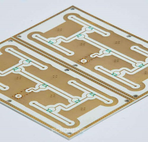
| Hypothetical twelve-by-eight-millimeter landing | Removed area | Remaining area |
|---|---|---|
| Outside radius 1 mm | 0.8584 mm² | 95.1416 mm² |
| Outside radius 2 mm | 3.4336 mm² | 92.5664 mm² |
| Independent straight-neck width change: 2 to 1.6 mm | 25% resistance increase | Fixed length, thickness and resistivity |
A radius needs a defined purpose
A rounded copper corner on a ceramic PCB can change the attachment area, the path available to current, the spacing to another conductor and the local geometry used in a mechanical model. These are different design questions. A radius selected to fit a manufacturing process is not automatically the optimum radius for a die landing or a narrow current turn. Before editing the layout, identify the problem the change is meant to solve and the evidence that will demonstrate improvement. The copper thickness guide explains the broader tradeoffs associated with thick metallization. This article addresses the smaller but consequential task of specifying and checking its corners.
Distinguish three features that drawings often confuse
Separate an outside corner of a copper island, an inside corner where a copper boundary turns into a recess, and a corner of the ceramic perimeter. Rounding an outside copper corner generally removes copper from its original rectangular envelope. Adding a fillet at an inside copper corner can add copper into the adjacent open region. Changing the ceramic outline is a separate fabrication and handling decision. Use different callouts and feature identifiers for these operations. A generic note saying all corners are rounded can otherwise remove required attachment area, reduce an electrical gap or unintentionally alter a substrate that was meant to remain rectangular.
Specify the plane of the finished copper contour
An etched copper feature has height, so its outline at the upper surface need not match its outline at the ceramic interface. Remtec's DBC design rules explicitly define copper feature measurements at the ceramic and copper interface unless otherwise noted. That is a supplier-specific convention worth resolving before a drawing is released. If the functional requirement concerns the top landing surface, identify that surface separately. A radius measured from a top-view image cannot automatically establish the radius at the bottom of a tapered copper wall. The DBC process guide provides context for why artwork and finished three-dimensional geometry should be distinguished.
Ask for a controlled contour rather than an unexplained minimum
A radius callout should state the nominal geometry and its permitted variation, or define an acceptable profile envelope where that better describes the function. Consider whether a tangent transition into the adjoining straight edges is important. A small flat, nick or abrupt transition may satisfy a loosely fitted circle while changing the local shape that matters to the application. Request the supplier's proposed finished contour and inspection approach for the selected copper thickness. Do not invent a universal rule that the radius must equal a particular multiple of thickness. A useful requirement connects the manufactured feature to an actual space, attachment or validation constraint.
Worked geometry: the area removed from a landing
Consider an invented rectangular copper landing twelve millimeters long and eight millimeters wide, with all four outside corners rounded inward at the same radius. Its original area is ninety-six square millimeters. The removed area is the difference between four radius-sized squares and four quarter circles, or four minus pi multiplied by the radius squared. At a one-millimeter radius, the removed area is about 0.8584 square millimeters, leaving 95.1416 square millimeters. The reduction is approximately 0.894 percent. At a two-millimeter radius, the reduction becomes 3.4336 square millimeters, or approximately 3.577 percent. These are exact planar geometry calculations under the stated assumptions, not process allowances.
Total landing area does not establish die support
The modest area reduction in that example can conceal a local conflict with a die corner. A rectangular die placed near the original landing boundary may project into the removed region even when the remaining copper area is much larger than the die area. Overlay the maximum die envelope, the permitted placement displacement and the required attachment margin on the minimum finished landing. Evaluate the corner region itself instead of comparing only two total areas. Include the intended die rotation and the actual reference used by the placement machine. If the mounting design deliberately permits overhang, document that decision and its assembly evidence rather than treating missing support as an accidental consequence of rounding.
Check the adjacent gap after adding an inside fillet
At an inside copper corner, a fillet can occupy space that previously belonged to an insulating gap. The relevant distance is the shortest distance between the finished conductor boundaries, including their allowed profile variation. A centerline spacing or a nominal distance between straight portions may miss the closest point near the new arc. Perform a geometric clearance check on the complete revised contour and repeat it for credible worst-case dimensional states. This exercise checks the drawing geometry only. It does not establish the required electrical clearance or creepage for a working voltage, contamination condition or insulation system. Those requirements must be determined independently for the intended equipment.
Treat a current turn as an electrical field problem
Current entering a broad island through a narrow neck will not necessarily occupy the copper uniformly. A radius may change the local current distribution, but its effect depends on the terminals, the nearby boundaries and the available cross section. Compare electrical loss and the location of concentrated current for the actual connection arrangement. Keep current, temperature-dependent resistivity, copper thickness and terminal boundary conditions the same when comparing candidate shapes. Do not convert a visually smoother turn into an unsupported current rating. The important result is whether the finished geometry meets the electrical and thermal requirements of the circuit, including the attached connections.
Check minimum neck width independently of the radius
A layout change intended to improve a corner can inadvertently narrow a neighboring neck. Record the minimum finished conductive width through the modified region and the thickness used in any resistance estimate. For a simple hypothetical straight segment, resistance is resistivity multiplied by length and divided by cross-sectional area. If length, thickness and resistivity remain fixed while width falls from two millimeters to 1.6 millimeters, the calculated resistance rises by twenty-five percent. A real turn is not the same as that straight segment, but the example exposes why a radius adjustment must not obscure a separate loss of cross section. Review both features on the revised drawing.
Keep local shape separate from substrate bending
A rounded island corner is not a complete solution to substrate bending. Rogers' discussion of DBC and AMB design identifies several contributors, including substrate proportions, panel orientation, layout and copper and ceramic thickness. Use that as a reminder to control the complete comparison. If a prototype with a revised radius also changes copper coverage on the opposite side, any change in measured flatness cannot be attributed to the radius alone. Record the global copper pattern and the measurement state of the part. A local contour trial should be planned so that the observation answers the original question instead of mixing several unrelated design changes.
Model a realistic feature when investigating mechanical behavior
If the reason for adding a radius is mechanical, define the applied temperature history, constraints, joining layers and material assumptions before interpreting a stress plot. A perfectly sharp ideal corner may produce a numerical peak that depends strongly on mesh size. That peak is not automatically a measurable failure criterion. Compare a realistic manufactured contour, examine mesh sensitivity and choose an evaluation quantity appropriate to the failure mechanism being investigated. A larger radius can also remove or redistribute material, so the comparison should document those geometric changes. Mechanical analysis is most useful when it guides a specific experiment or inspection, rather than producing a colorful image without a decision rule.
Agree on how the radius will be measured
For an optical inspection, specify the viewing surface, magnification or calibrated scale, illumination method and treatment of edge roughness. Decide whether acceptance is based on a fitted radius, a profile overlay or a minimum distance from a protected envelope. These methods answer different questions. A fitted circle can average over local departures; a profile envelope can expose them but may be more sensitive to segmentation. Use representative parts to confirm that different inspectors obtain sufficiently consistent results for the decision. If the critical contour lies beneath an overhanging upper edge, determine whether another measurement method or a sectioned sample is necessary.
Resolve digital export and supplier compensation
Check that the exported fabrication data preserve arcs or approximate them with sufficient resolution for the agreed contour tolerance. A coarse polygon approximation can introduce corners that were absent in the design system. Keep the design master separate from any supplier compensation used to achieve the finished geometry, and document who controls that compensation. When a supplier returns a manufacturability proposal, compare the resulting finished feature with the functional envelope rather than simply accepting every change to the artwork. A revision comparison should identify which copper islands, gaps and landing regions changed so that assembly engineering can review the effects efficiently.
Use a small, interpretable prototype comparison
An effective trial might compare two or three candidate radii while holding the ceramic grade, thickness stack, copper layout away from the trial region and assembly method fixed. Inspect the delivered contours before testing the assembled devices; otherwise the experiment may compare nominal drawings instead of actual parts. Record the response relevant to the reason for the change, such as attachment coverage, electrical loss or a defined mechanical observation. Include enough repeated specimens to reveal whether variation within a group overwhelms the difference between groups. No particular sample count is universal. Select the experiment with the reliability and manufacturing teams for the decision it must support.
Release the geometry with its functional checks
The final drawing package should connect each important radius to a finished surface, a tolerance or profile definition and an inspection method. Preserve the minimum landing envelope, conductor gap and neck width as independent requirements. Include the approved supplier feedback and identify any prototype evidence used to select the contour. If a later change in copper thickness or fabrication process alters the finished shape, revisit those checks rather than transferring the old radius note unchanged. The manufacturing specification guide can help organize the release package. A corner radius becomes an engineering control when everyone can identify the same feature, measure it consistently and explain why its permitted range is appropriate.
Engineering example
The radii, pad dimensions and neck widths are invented geometry examples. They are not recommended process limits, electrical spacings or qualified mechanical improvements.
Before you release the design
- Distinguish copper outside corners, inside corners and ceramic outline corners.
- Identify the finished contour measurement plane.
- Overlay the die placement envelope on the minimum landing.
- Recheck conductor spacing and minimum neck width.
- Validate the intended benefit with controlled comparisons.
Sources and further technical reading
Manufacturer references support the material and process context. Worked examples and checklists are engineering guidance; they are not test results or supplier guarantees.