
| Hypothetical case | Calculated result | Condition |
|---|---|---|
| 24 V across10 Ω | 57.6 W | Defined resistance state |
| 24 V across12 Ω | 48 W | Constant voltage |
| 2.4 A through12 Ω | 69.12 W | Constant current |
| 26.4 V across9.5 Ω | 73.36 W | Illustrative high-power tolerance combination |
| 24 V PWM,50%duty,10 Ω | 28.8 W average | Constant resistance within cycle |
| 500 J stored /25 W net | 20 s | Ideal energy estimate |
Identify the heater construction and the required heat delivery
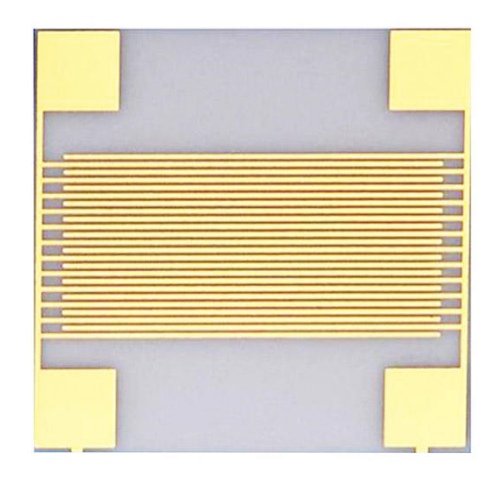
A ceramic heater can contain an embedded resistive element, a printed surface circuit or another qualified heating structure. The ceramic may provide insulation, mechanical support and a path for distributing heat, while the resistor defines how electrical input becomes heat. Kyocera describes a co-sintered embedded-element construction for its ceramic heaters, illustrating why the circuit and ceramic should be specified as one product system. The ceramic heater guide introduces the product family. Start a design inquiry with the object being heated, required temperature distribution, warmup behavior, supply conditions and mounting arrangement rather than asking only for a particular resistance or maximum power density.
State the temperature and method for the resistance requirement
Resistance depends on the element material and its temperature, so a value without a measurement condition can be ambiguous. Specify the reference temperature, allowed tolerance and measurement method for receiving inspection. Use sufficiently low measurement power where necessary to avoid changing the temperature being measured. Keep lead and contact resistance separate when they are significant compared with the element. The operating resistance may differ from the receiving value and should be supported by the selected construction's data or measurements. Do not assume every ceramic heater is self-regulating or has the same temperature coefficient merely because the insulating body is ceramic.
Calculate electrical power at the actual heater terminals
For a resistive element at a defined state, power can be calculated as voltage squared divided by resistance, or current squared multiplied by resistance. In an invented example, twenty-four volts across ten ohms produces 2.4 amperes and 57.6 watts. These values refer to the heater terminals, not necessarily the output setting of a supply separated from the heater by resistive wiring. Include voltage drops and other dissipative components at their actual locations. A wiring loss is not useful heater output simply because it appears in the input-power measurement. Keep the electrical boundary explicit when comparing a bench result with the requested heating function.
Distinguish constant-voltage and constant-current behavior
If the element resistance rises with temperature, constant-voltage operation reduces electrical power, while constant-current operation increases it. Consider the same invented element rising from ten to twelve ohms. At twenty-four volts, power falls from 57.6 watts to forty-eight watts. At a maintained current of 2.4 amperes, power instead rises to 69.12 watts. Neither case describes a particular commercial heater. The example shows why a resistance-temperature relationship must be interpreted together with the drive method. Obtain the actual permitted operating conditions and control strategy for the selected product rather than treating resistance change as inherently stabilizing under every electrical supply.
Use a temperature coefficient only within its justified range
A linear approximation can express resistance as a reference value multiplied by one plus a temperature coefficient times the temperature change. If an assumed coefficient is one thousand parts per million per kelvin, a two-hundred-kelvin increase gives a twenty-percent resistance increase in that linear model. That reproduces the invented ten-to-twelve-ohm example. Real heating materials can require a nonlinear curve or a restricted fitting interval. Kyocera's heater data sheet notes that different heating materials with different temperature coefficients are available; it does not establish one universal curve. Use the selected element's controlled data and verify the operating range relevant to the application.
Budget supply variation and resistance tolerance together
The nominal power is not necessarily the maximum electrical input. Suppose the invented twenty-four-volt supply can vary by ten percent and the ten-ohm reference resistance by five percent. At the reference temperature, the highest combination is 26.4 volts across 9.5 ohms, giving approximately 73.36 watts. The lowest combination is 21.6 volts across 10.5 ohms, giving approximately 44.43 watts. These are tolerance examples, not a heater rating. Evaluate the appropriate combinations at startup and during operation using the actual resistance-temperature behavior and controller limits. A nominal wattage alone cannot demonstrate that the supply, leads and heated assembly remain within their required conditions.
Define the area behind a watt-density statement
Power density can be reported using the complete ceramic face, a specified active heating area or the footprint of the resistive circuit. Those denominators are different. The invented 57.6-watt heater would average 14.4 watts per square centimeter over a four-square-centimeter active area, but 57.6 watts per square centimeter over a one-square-centimeter resistor footprint. Neither figure describes the local peak temperature or proves an acceptable heat flux into the load. State the area and the physical boundary whenever reporting watt density. For a patterned heater, retain the spatial distribution as well as the average so that a narrow region is not hidden by a large overall ceramic area.
Separate electrical dissipation from useful heat into the load
Not all electrical heat necessarily enters the target object. Some can leave through exposed surfaces, fixtures, terminals or other paths. Define the thermal boundary of the useful load and estimate or measure those competing paths. At steady temperature, the electrical input balances heat leaving the assembly; during warmup, some input also increases stored thermal energy. A high nominal watt density does not guarantee fast heating if much of the input is diverted into a fixture or a large surrounding mass. Conversely, a poorly coupled heater can become hot while transferring insufficient heat to the intended object. Evaluate heater temperature and load temperature as separate quantities.
Use an energy estimate to check a warmup request
Assume an invented combined heated mass with an effective heat capacity of five joules per kelvin and a required temperature increase of one hundred kelvin. The stored-energy change would be five hundred joules under a constant-heat-capacity approximation. With a constant net twenty-five watts available for that storage, the ideal time is twenty seconds. This is not a prediction of a real heater's ramp rate. It excludes changing losses, nonuniform temperatures and temperature-dependent properties. Use the estimate to identify an inconsistent request or an omitted thermal mass, then verify the actual warmup curve with the real mounting and load.
Interpret PWM power using the applied waveform
For an ideal resistive element whose resistance remains effectively constant during a pulse cycle, switching twenty-four volts on for half the cycle produces half the continuous electrical power. With ten ohms, that average is 28.8 watts. Squaring the average voltage of twelve volts would incorrectly give 14.4 watts; power depends on the mean of voltage squared, or equivalently the appropriate RMS voltage. Real control systems may include current limiting, changing resistance and other effects, so evaluate the actual waveform. Record the controller mode and limits with the heater specification instead of relying only on a percentage displayed by a user interface.
Design the heating pattern for the load distribution
Uniform electrical generation does not automatically produce a uniform load temperature. Edge losses, mounting contacts, changing load thickness and nearby heat sinks can create different local conditions. Define the temperature uniformity requirement over a specified area and at a specified operating state. A patterned or multizone heater may be useful, but its control and sensing arrangement must support the intended correction. Avoid judging uniformity solely from a picture of an unloaded heater glowing or from one central sensor. Map the relevant temperatures under the production load and use those observations to refine the heating distribution and mounting interface.
Treat the mounting interface as part of the design
Specify the contact surface, support, interface material where used and the method of retaining the heater. The mounting arrangement affects heat transfer and mechanical loading as the assembly changes temperature. Watlow's ULTRAMIC product information makes its performance dependent on the application, heater design and process parameters; its headline capabilities are not universal values for every installation. Obtain the selected product's mounting guidance and qualify the intended arrangement. Do not infer that a higher clamping force or a thinner interface is always better. The objective is a reproducible thermal contact that the complete heater and load assembly can tolerate through the required operating cycle.
Place sensing and independent limits around the actual hot regions
Choose sensor locations that can represent the controlled load and any heater region that needs a separate limit. A sensor attached to the load may respond more slowly than the element when contact is lost or the load is removed. Define the allowed behavior during startup, normal control, sensor failure and the relevant abnormal conditions identified by the product design. Keep the lead and terminal conditions within the selected heater's specification as well as the active heating surface. These requirements belong to the complete heating system. A resistance calculation or material temperature capability cannot by itself establish the behavior of the controller and its protective functions.
Verify electrical and thermal requirements together
A useful first-article test records terminal voltage, current, resistance state, heater and load temperatures, mounting details and the operating sequence. Compare startup and steady operation, then include the required repeated cycles and environmental conditions. If measured power differs from the simple calculation, check the waveform, terminal voltage and resistance temperature before attributing the discrepancy to the ceramic. Preserve the measurement locations and uncertainty so that later production tests are comparable. The manufacturing specification guide can organize the report. Electrical acceptance and thermal acceptance should remain linked, because the same cold resistance can produce different load behavior in different assemblies.
Release a heater specification with a complete operating envelope
The released specification should identify construction, reference resistance and tolerance, operating resistance information, supply and control limits, active area, temperature requirements and mounting conditions. Include the warmup and uniformity tests that demonstrate the intended function. State which changes to the load, fixture, controller or element require review. A ceramic heater is correctly specified when its electrical input and thermal output are connected through a verified assembly and operating envelope. Neither a low resistance nor a high catalog watt-density figure alone establishes that the product will deliver the required temperature safely, uniformly and repeatably in the intended equipment.
Engineering example
Every electrical and thermal numerical example is hypothetical. No catalog maximum temperature, watt density or ramp rate is generalized to an unqualified installation.
Before you release the design
- State reference resistance temperature and measurement method.
- Model the actual voltage, current or PWM drive behavior.
- Define the area used for watt density.
- Include the load, fixture, contact and competing heat paths.
- Verify sensing, limits and the complete warmup and operating cycle.
Sources and further technical reading
Manufacturer references support the material and process context. Worked examples and checklists are engineering guidance; they are not test results or supplier guarantees.