
| Hypothetical case | Result | Boundary |
|---|---|---|
| 300 kW shared by eleven remaining units | 27.27 kW per unit | No overload capability implied |
| 30 kW at 400 V versus 800 V | 75 A versus 37.5 A | Output current only |
| One milliohm output connection | 5.63 W versus 1.41 W | Not semiconductor loss |
| 700 W / (0.03 kg/s × 3800 J/kg K) | 6.14 K | Bulk coolant rise only |
Locate the carrier inside the charging system
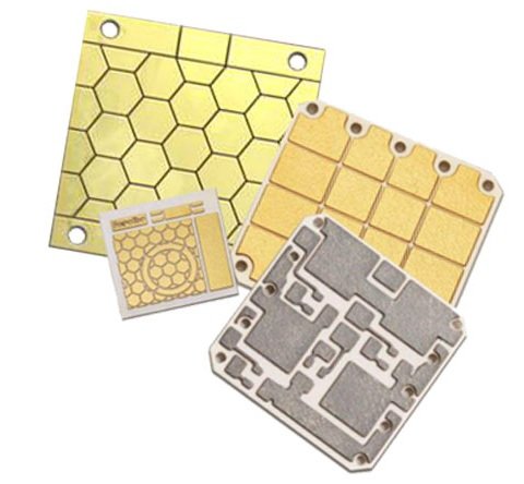
A ceramic circuit carrier is one component within a power conversion assembly, not the complete fast charger. Begin by distinguishing the charging cabinet, its replaceable power subunits, the semiconductor module and the internal ceramic substrate. A control board elsewhere in the cabinet may use a different construction. Define which part is being designed or purchased before discussing ceramic performance. Infineon's DC charging overview describes power subunits used to build higher-power systems, while TI distinguishes power factor correction and DC conversion stages. These architectural descriptions provide context; they do not mean that every board or every charging topology requires a ceramic carrier.
Translate station power into the actual subunit duty
A station power rating cannot be assigned directly to one ceramic tile as either electrical load or heat. Identify the number of active subunits, their sharing strategy and the output conditions each can encounter. In an invented example, twelve equal subunits delivering twenty-five kilowatts each provide three hundred kilowatts in total. If one is unavailable, keeping the same station output would require the remaining eleven to deliver about 27.27 kilowatts each, an increase of roughly 9.1 percent. This calculation does not authorize overload operation. It identifies a system decision: either the design supports that condition or the station must reduce its available output.
Separate semiconductor technology from carrier construction
The choice of IGBT, silicon carbide or gallium nitride devices changes the electrical and packaging questions, but it does not specify the ceramic by itself. A packaged discrete device, a purchased module and a custom die assembly present different design boundaries. For a purchased module, internal substrate choices may already be controlled by its manufacturer. For a custom assembly, the team must qualify the ceramic, conductor pattern, attachment and interconnections together. The SiC power module guide helps frame that packaging discussion. Avoid asking a substrate supplier to guarantee the performance of a converter whose device and assembly interfaces remain undefined.
Build a loss map across the operating envelope
Use a set of relevant input, output and load conditions rather than one headline efficiency number. Assign conduction, switching and other losses to their physical locations with a documented calculation or measurement basis. Separate semiconductor heat entering the carrier from losses in magnetics, bus connections, capacitors and auxiliary supplies. At light load or a different output voltage, the distribution can change even when station power decreases. Preserve the converter operating mode associated with each loss case. A useful carrier requirement specifies the spatial heat sources and their combinations, allowing thermal analysis to address the region that actually becomes limiting.
Check the current demanded at different output voltages
Constant output power does not imply constant output current. For a hypothetical thirty-kilowatt subunit, a four-hundred-volt output requires seventy-five amperes, while an eight-hundred-volt output requires 37.5 amperes. If an illustrative output connection has one milliohm of resistance, those currents produce approximately 5.63 watts and 1.41 watts of loss respectively. These are output connection examples, not the current or loss of every semiconductor inside the converter. The topology determines internal waveforms. Use the comparison to ensure that the lower-voltage operating region is represented in the electrical and thermal assessment instead of evaluating the module only at its maximum voltage.
Choose materials against the identified limiting path
Compare alumina, aluminum nitride, silicon nitride or another qualified construction using the complete stack and the actual failure concerns. A material with higher nominal conductivity may offer little system benefit if the lower interface dominates the temperature rise. A mechanically demanding attachment or cycling requirement can also influence the preferred construction. Keep thickness, conductor pattern, die arrangement and cooling contact explicit during comparisons. The ceramic material selection guide organizes these tradeoffs. A successful selection explains which requirement improved and which evidence supports the improvement; it should not rely on assigning one ceramic material to all fast-charging power levels.
Evaluate coolant conditions at the local module
For a liquid-cooled assembly, the relevant boundary is the coolant condition at the module, not merely the chiller set point. In an illustrative energy balance, seven hundred watts added to a coolant stream of 0.03 kilograms per second with a specific heat of 3,800 joules per kilogram kelvin raises its bulk temperature by about 6.14 kelvin. The calculation assumes steady flow and the stated properties, with no other heat exchange. It does not predict wall or junction temperature. Document the actual coolant composition and temperature-dependent properties, and account for how the piping arrangement determines the inlet condition seen by each subunit.
Include neighboring loads in shared cooling assessments
Subunits that share a cooling circuit or air path can influence one another. Determine whether the assessed module receives fresh coolant or air, or a stream already warmed by another load. For parallel liquid branches, verify the relevant flow distribution rather than assuming each branch receives an equal fraction under every condition. For air cooling, identify recirculation and upstream heating in the intended enclosure. A bench test with an isolated cooler can establish component behavior without representing the cabinet boundary. Keep both levels of evidence and state how the cabinet test confirms that the ceramic assembly remains within its intended operating conditions.
Preserve the thermal interface during service and assembly
Fast-charging equipment often uses modular construction to simplify manufacturing and maintenance, but a replaceable subunit still needs a controlled thermal interface. Specify the surface preparation, interface material, mounting sequence and permitted reuse or replacement procedure supported by the assembly design. Do not infer that a removed interface can be reused because the ceramic appears undamaged. Where a carrier is internal to a sealed or purchased semiconductor module, follow that module's defined installation boundary. Where the ceramic itself is mounted by the equipment builder, verify that the fixture and clamping arrangement do not introduce uncontrolled bending or concentrated loading during assembly.
Connect layout decisions to switching behavior
A ceramic carrier can support a compact power stage, but the complete commutation path includes more than its visible copper. Identify device terminals, attachment structures, bond wires or clips, bus connections and local capacitors. Keep the gate drive reference path distinct from the high-current return where the design requires it. The IGBT module application guide and the SiC guide provide application context, while the actual parasitic and switching assessment belongs to the selected construction. Do not promise a switching speed or voltage margin from ceramic choice alone. Use representative measurements and models that include the external connections used in the charger.
Distinguish heat-transfer insulation from system isolation
The ceramic may provide electrical separation across a heat-transfer path, but the charger has several insulation boundaries with different functions. Draw the intended potentials of conductors, baseplates, coolers, sensing circuits and accessible structures. Identify which requirements apply to each boundary through the responsible product safety process. A material dielectric-strength value does not establish the working-voltage rating of a patterned, assembled module. Surface paths, edges, mounting hardware and environmental conditions must be considered where applicable. Use the creepage and clearance guide to organize those questions without treating a generic spacing example as certification of the complete charging system.
Specify a mission profile relevant to charging use
The carrier's temperature history depends on how the charger is operated, not just the semiconductor's maximum rating. Describe charging sessions, idle periods, ambient conditions, power sharing and any operating transitions that materially affect the assembly. Distinguish slow changes in the cooler from faster device temperature swings. The resulting profile should guide the selection of relevant qualification evidence for joints, metallization and ceramic integrity. Do not replace that analysis with a cycle count copied from an unrelated substrate demonstration. Test conditions, geometry and failure criteria must be understood before a published cycling result can support a claim about the proposed assembly.
Design sensing and derating around observable quantities
A temperature sensor reports the condition at its own location. Document how that reading relates to the component or interface whose limit controls operation. The relationship may change with output voltage, current, cooling flow or the number of active subunits. Define the derating behavior through the converter control design and verify it under representative conditions. Do not use a favorable ceramic surface temperature to infer that every die remains acceptable. TI's charging module overview includes accurate sensing and control among its design requirements; the carrier assessment should therefore provide the thermal information that the control team needs rather than end at a material comparison.
Qualify abnormal operating cases at the right level
The ceramic supplier cannot independently validate the charger's response to a cooling fault, failed subunit or electrical disturbance. Identify the cases the product design must address and assign each verification to the responsible assembly or system team. The substrate contribution may include dimensional stability, insulation behavior or attachment integrity under a defined exposure. Keep these requirements separate from converter protection behavior and station-level availability. A successful normal-operation thermal test is not evidence for every abnormal condition. Document the tested configuration and any required operating restrictions so that manufacturing or service changes do not silently invalidate the basis for acceptance.
Compare quotations using the same assembly boundary
A metallized ceramic tile, a die-attached substrate and a complete power module are different purchases. Request quotations that identify the supplied ceramic grade, conductor construction, finish, inspection scope and any included assembly or testing. Include traceability expectations and the process for approving material or metallization changes. A lower tile price does not necessarily reduce the cost of an accepted power subunit if it changes attachment yield, inspection requirements or cooling hardware. Keep the carrier comparison connected to the complete manufacturing route and delivered function. This makes the commercial decision useful to both the substrate buyer and the team accepting the converter.
Release evidence for the operating range, not one point
A practical fast-charging carrier package includes the controlled drawing, stack description, assembly interfaces, loss map, cooling boundary and relevant qualification results. It also identifies the operating combinations used to verify temperature and electrical behavior. Preserve the distinction between an analysis assumption, a supplier typical property and a measured production result. If the subunit supports only part of the station's possible power range, make that limitation explicit in the system design. Ceramic carriers can provide useful thermal and electrical functions within a charger, but their value is demonstrated through the actual module construction and its operating envelope rather than the station power label.
Engineering example
All numerical inputs are hypothetical. Examples do not establish device ratings, approved overload, working voltage or charger certification.
Before you release the design
- Separate station, subunit, module and carrier boundaries.
- Map losses across output voltage and loading conditions.
- Evaluate the local cooling boundary and shared loads.
- Preserve installation and service interface controls.
- Verify the intended operating range with representative assemblies.
Sources and further technical reading
Manufacturer references support the material and process context. Worked examples and checklists are engineering guidance; they are not test results or supplier guarantees.