
| Illustrative geometry | Result | Meaning |
|---|---|---|
| 8 mm center-to-edge minus 3.5 mm washer radius | 4.5 mm | Projected nominal gap |
| 4.5−0.3−0.2 mm | 4.0 mm | Projected envelope only; not an acceptance limit |
Begin with the assembled mounting arrangement
A mounting hole changes more than the mechanical outline of a ceramic substrate. Its wall, nearby metallization, fastener, washer and supporting structure can create additional electrical paths that are absent from the bare tile drawing. Evaluate the assembled construction before assigning a creepage distance to the hole region. Identify the conductors that must remain separated and the potential of the mounting hardware. The ceramic hole design guide addresses manufacturing considerations, while this article focuses on how to document and inspect the insulation geometry around the finished mounting feature. It does not prescribe a universal spacing or certify an assembly.
Keep creepage, clearance and solid insulation distinct
Creepage concerns a path along an insulating surface, while clearance concerns a path through air. Solid insulation is a separate part of the insulation assessment. TI's isolation guidance illustrates the difference between surface and air distances on a component package. The same distinction helps organize a ceramic mounting review, but the component example does not supply a spacing requirement for a ceramic board. A longer path drawn around a hole may coexist with a much shorter air path to a screw or washer. Review each relevant path type rather than combining them into one distance labeled isolation.
Identify the applicable requirements before measuring compliance
The required distances depend on the product and its insulation requirements, not only the nominal operating voltage. The IEC publication page for IEC 60664-1 describes insulation coordination and the treatment of clearances, creepage distances and solid insulation within its stated scope. That public description is not the full standard or a substitute for the applicable product requirements and amendments. Have the responsible design or compliance team identify the governing requirements and measurement rules. Then use the actual assembly geometry to evaluate them. The creepage and clearance overview is a starting point for organizing inputs, not an approval of any particular mounting design.
Assign a potential to each metal part
Mark the upper conductors, lower metal, plated hole surfaces, screw, washer, standoff and cooler on a simple connection diagram. Identify intentional electrical connections and any metal whose potential is not defined by the design. A screw that contacts a grounded chassis should not be treated as an empty insulating hole. Likewise, a lower metallized surface connected elsewhere in the assembly may create a different boundary from the one visible in the top artwork. Do not assume that two separated metal objects remain at the same potential merely because they are mechanically adjacent. Resolve the intended electrical relationships before measuring distances between them.
Distinguish a plain hole from a metallized hole
A hole with an insulating ceramic wall is a different construction from one with deliberate metallization, an edge wrap or a conductive insert. Specify the supplied condition explicitly, including whether metal is allowed to approach or enter the hole. Inspection should verify that the finished part matches that definition. A drawing symbol for a mounting hole may not communicate all of these surface conditions. Review the top and bottom patterns together and include the relevant section view. The actual conductive boundary is what matters for the assessment; it should not be inferred from the nominal drill or laser diameter alone.
Measure to the hardware envelope rather than the hole center
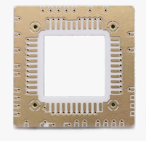
For a simple hypothetical top-view check, suppose a conductor edge is eight millimeters from a fastener center. A washer with a maximum radius of 3.5 millimeters leaves a projected nominal gap of 4.5 millimeters. If the assembled hardware can move 0.3 millimeters toward the conductor and a relevant metal feature extends another 0.2 millimeters, the projected remainder becomes four millimeters. These invented values illustrate an envelope calculation only. They are not required or acceptable clearances, and a top-view projection does not establish every three-dimensional path. Use the full hardware shape and mounting tolerances for the actual assessment.
Include the underside and hole wall in the model
A conductor on the lower face may approach the mounting feature more closely than the upper pattern suggests. Inspect paths involving the hole wall, the lower ceramic surface and the supporting hardware. Also review whether the substrate overhangs a metal support or whether a standoff enters the hole. A single top-view keepout cannot describe all of these relationships. Use cross sections at the closest approaches and identify which surfaces are insulating in the assembled condition. If the lower surface is hidden after mounting, define an inspection or manufacturing control that verifies the relevant geometry before it becomes inaccessible.
Do not automatically credit a detour around an opening
It can be tempting to draw a long surface route around a hole and count that line as the creepage distance. The accepted measurement depends on the applicable rules and the actual feature dimensions and condition. Narrow grooves, slots, joints and openings may be treated differently under different requirements. Avoid inventing a rule that every hole adds its circumference or that every slot adds two wall depths. Document the proposed path and have its treatment confirmed against the governing requirements. Separately check the shortest relevant air path, since removing material to lengthen a surface path does not necessarily increase clearance to nearby conductive hardware.
Treat edge quality as part of the finished geometry
The ceramic edge around a hole may differ from its nominal CAD outline because of taper, chamfer, chipping or process variation. Define which finished dimensions are controlled and which edge conditions are acceptable for the intended construction. Review the effect of permitted material loss on the local path rather than assuming the nominal boundary always exists. Do not turn an illustrative chip size into a general acceptance rule. Where damage raises concern about cracking or insulation integrity, use the responsible engineering disposition process. A part that meets its nominal hole diameter may still need examination if its local edge condition differs from the approved specification.
Account for mounting movement and tolerance accumulation
A hole can allow the substrate to shift relative to a screw, and a washer can shift relative to the screw. The conductor pattern also has positional tolerances relative to the ceramic features. Identify the tolerances that can move the relevant boundaries toward one another, taking care not to count the same variation twice. For a conservative simple stack, add the applicable worst-case movements rather than relying on a nominal assembly position. If a statistical stack is proposed, document its distribution and independence assumptions and confirm that the governing requirement permits the method. Preserve the datums used by both the substrate supplier and the assembly team.
Review insulating washers and sleeves as components
An insulating washer or sleeve may change the construction, but its presence alone does not establish a qualified insulation barrier. Specify its material, geometry, installation and relevant environmental capability through the product design process. Include the path around its edges and the interfaces between separate parts. Check whether compression, movement or assembly variation changes the intended coverage. A sleeve that is missing, incorrectly seated or replaced with a different part can invalidate the original geometry. Make the required component identifiable in the bill of materials and assembly instructions rather than relying on an informal instruction to add insulation near the screw.
Keep contamination assumptions tied to the enclosure
The surface condition around mounting hardware can be affected by processing residues, handling, condensation or the operating environment. Determine the applicable environmental assumptions with the product team and identify how the enclosure and assembly process support them. Do not assume that the ceramic's appearance guarantees a clean insulating surface throughout service. Likewise, a coating or encapsulant should not receive an automatic spacing credit without evaluation under the applicable requirements and controlled process. The assessment should identify the actual surface and interface being relied upon, including areas beneath washers or near joints that may be difficult to inspect after assembly.
Coordinate mechanical loading with the insulation design
The mounting arrangement must hold the assembly without creating an uncontrolled local load on the ceramic. Review the contact surfaces, support and permitted installation procedure with the substrate and module suppliers. A mechanical change that improves retention can alter the location of conductive hardware or the shape of an insulating interface. Conversely, enlarging an electrical keepout can reduce available mounting or heat-transfer area. The mechanical mounting guide provides related design considerations. Resolve these requirements together on the released assembly drawing rather than treating the electrical keepout and mechanical fixture as unrelated decisions made by separate teams.
Make the inspection plan match the critical paths
Define which dimensions and surface conditions must be verified on the substrate and which must be verified after assembly. Include hardware identity, washer diameter, seating position and any insulating components that establish the assessed configuration. Use measurement methods with sufficient access and resolution for the feature being checked. Retain clear records of the inspected datum and path so that a later reviewer can reproduce the interpretation. A generic visual inspection of the finished module may not reveal the shortest path beneath hardware. If a critical feature becomes hidden, plan its verification at an earlier manufacturing stage and preserve traceability to the assembled unit or lot.
Use electrical tests within their proper scope
An electrical test under specified conditions can provide evidence for the tested insulation construction, but it does not automatically resolve an incorrect spacing assessment or an uncontrolled assembly variation. Identify the test purpose, configuration, environment and acceptance criteria through the applicable engineering and compliance process. Keep test records linked to the hardware and substrate revision used. Do not infer a continuous working-voltage rating from a single withstand result without the required basis. Likewise, a successful bare-tile test does not establish the behavior of the mounted assembly if screws, lower metal or interfaces introduce additional paths after that test.
Preserve the verified arrangement through changes and service
The final documentation should show the relevant conductive boundaries, insulating surfaces, datums, tolerance assumptions and governing requirements. Reference the approved hardware and installation instructions, including any replacement restrictions needed to preserve the construction. Evaluate later changes to washer size, fastener type, substrate thickness or metallization against the original assessment. A mounting hole is often reused across product revisions, which can conceal changes to nearby conductors or the supporting structure. Treat the complete mounting region as a controlled electrical and mechanical interface. That approach makes creepage review reproducible and prevents a nominal hole dimension from standing in for the assembled insulation design.
Engineering example
Dimensions are hypothetical and do not specify required creepage or clearance. Applicable product requirements, complete geometry and qualified assessment control acceptance.
Before you release the design
- Identify the potential of hardware and all nearby metal.
- Review plain versus metallized hole construction.
- Measure complete hardware envelopes in three dimensions.
- Confirm path treatment against applicable requirements.
- Preserve the inspected mounting configuration through revisions.
Sources and further technical reading
Manufacturer references support the material and process context. Worked examples and checklists are engineering guidance; they are not test results or supplier guarantees.