
| Hypothetical calculation | Result | Boundary |
|---|---|---|
| 10 MPa × 25 mm² | 250 N | Ideal uniformly loaded area |
| 10 MPa × 400 mm² | 4,000 N | Not a process recommendation |
| 50 µm / (150 W/m·K × 25 mm²) | 0.01333 K/W | Homogeneous layer only |
| 100 W × 0.01333 K/W | 1.33 K | Excludes interfaces and spreading |
Name the attachment interface before selecting a paste
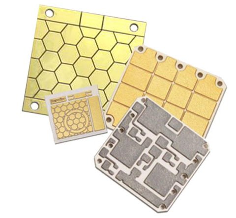
Silver sintering can be considered at more than one location in a ceramic power assembly. A semiconductor may attach to the upper metallization, or the complete substrate may attach to a baseplate or cooler. Those joints differ in area, geometry, loading and inspection access. Start with a stack drawing that identifies the proposed sintered interface and the materials immediately above and below it. The power substrate guide gives context for the complete assembly. A paste selected for one attachment location should not be assumed suitable for another merely because both joints contain silver and the same ceramic appears somewhere in the stack.
Treat surface compatibility as a product-specific requirement
Heraeus lists different workable surfaces and processing categories for its individual sinter products, including pressure and non-pressure families. That product-level distinction matters more than a general statement that silver can be sintered onto metal. Identify the actual upper and lower surface materials, their thicknesses, underlying layers and condition when the joint is formed. A nominal finish name may conceal different layer sequences or preparation histories. Obtain compatibility guidance for the selected paste and construction. Do not transfer a process condition from a supplier's table to a different paste, exposed metal or attachment area without the supporting qualification and current controlled process documentation.
Separate the ceramic choice from the exposed joining surface
The sintering material normally encounters the substrate's exposed metallization, while the ceramic and its metal-to-ceramic joint form part of the supporting structure beneath it. These interfaces have different functions and failure possibilities. Selecting silicon nitride ceramic does not by itself specify the surface chemistry needed for silver attachment. Conversely, a compatible surface does not prove that the complete substrate will tolerate the assembly load or subsequent service conditions. Review the metal finish, copper pattern, ceramic thickness and lower support together. Keep the substrate manufacturer's joining system distinct from the later sintered attachment when documenting qualification results and investigating a failure.
Understand the process category without inventing a universal recipe
Heraeus' soldering and sintering whitepaper describes sintering as a solid-state joining route and distinguishes die attachment from larger module attachment. The important design consequence is that the material and process must be selected as a system; a solder reflow profile cannot simply be renamed as a sintering profile. Temperature, time, atmosphere, material preparation and applied pressure where used belong to the qualified process. This article does not prescribe those settings. Request the selected material's controlled instructions and confirm their applicability to the actual device and substrate. A broad technology comparison is useful background, but it is not a manufacturing traveler for a new assembly.
Translate nominal pressure into the actual force question
For a uniform ideal contact, force equals pressure multiplied by loaded area. Consider an invented pressure of ten megapascals on a five-by-five-millimeter area. The corresponding force is 250 newtons. Applying the same assumed pressure to a twenty-by-twenty-millimeter area requires four thousand newtons. These values are dimensional examples, not recommended settings. They show why moving from die attachment to large-area attachment changes the tooling question even if a pressure number appears unchanged. Identify the area over which the machine defines pressure, the actual contact arrangement and the way force reaches the joint. A machine setpoint alone does not describe the stress distribution inside the ceramic assembly.
Review support beneath patterned and uneven surfaces
A ceramic substrate may contain separated copper islands, gaps, local thickness changes or a backside shape that does not contact a support uniformly. Before applying an assembly load, determine how the part is supported and whether the load path crosses unsupported regions. Include the compliance and alignment of the tooling and the protection required for the device surface. A nominally flat fixture does not guarantee uniform support of a bowed or patterned part. Work with the substrate and assembly suppliers to define a suitable arrangement and verify it on representative hardware. Do not infer an allowable pressing force from a bare ceramic material-strength number alone.
Specify deposited material and final bond line separately
A wet print or dispensed deposit is an intermediate state, while the finished sintered joint is the state used in the thermal and mechanical design. State which thickness is being specified and how it will be measured. Deposition consistency, drying behavior, placement and the subsequent process can influence the final geometry. Record the permitted footprint and any keepout around adjacent conductors or protected surfaces. If a process change alters the final layer, review the assembly height and thermal model rather than checking only whether the original wet deposit dimension was met. A clear distinction between intermediate and final states makes supplier data and assembly measurements much easier to compare.
Use a layer calculation to identify sensitivity, not a guaranteed benefit
Assume a hypothetical homogeneous joint fifty micrometers thick, with an effective conductivity of one hundred fifty watts per meter kelvin and an area of twenty-five square millimeters. The one-dimensional resistance is about 0.01333 kelvin per watt. At one hundred watts passing uniformly through that area, the modeled drop is about 1.33 kelvin. Doubling the thickness doubles this layer term under the same assumptions. These numbers do not describe a named paste or an actual module. They exclude spreading, interface resistance and nonuniform bonding. Use such a calculation to understand which measurements matter, then evaluate the complete thermal path rather than presenting the layer estimate as a measured junction-temperature improvement.
Do not replace a measured effective property with bulk silver data
A sintered joint's effective behavior depends on its finished structure and interfaces. A bulk-metal property is therefore not automatically the correct value for every processed joint. Identify whether a quoted conductivity describes a particular test specimen, a typical processed material or a value assumed in a model. Record the temperature and method where available. If the design decision depends strongly on that property, request evidence representative of the intended process or examine a justified range. Keep the uncertainty visible in the SiC module thermal assessment. A highly precise calculation using an unjustified material value can be less useful than a transparent sensitivity study.
Separate distributed porosity from a missing attachment region
Inspection may reveal features at different scales and with different physical meanings. Distributed pores within a sintered layer are not necessarily equivalent to a large unbonded region at an interface. State which feature the inspection is intended to detect and how it is distinguished from normal material structure or imaging artifacts. Avoid borrowing a solder-void percentage as a silver-sinter acceptance rule without evidence. Retain the location, extent and interpretation of relevant indications, especially beneath a heat source or near a mechanically important boundary. The acceptance method should be developed for the actual joint construction and connected to functional and reliability evidence rather than chosen solely because it produces a convenient number.
Design mechanical tests to reveal the failure location
A shear or other mechanical test becomes more informative when it records where the assembly failed. Distinguish failure within the sintered layer, at either joining surface, in the substrate metallization system or in another component. Keep specimen dimensions, loading method, rate and prior conditioning controlled when comparing results. If a test coupon differs from the product in finish, area or thermal history, state the limitation. A larger force does not automatically establish a longer service life, and a strong attachment can shift failure into a different part of the assembly. Use the test to understand the complete interface system rather than ranking joints by a single number stripped of context.
Match exposure tests to the service mechanism
A power-cycling test and an externally imposed temperature-cycling test do not necessarily produce the same temperature distribution or mechanical loading. Choose qualification conditions that address the expected service mechanisms and identify what each test demonstrates. Record the monitored electrical, thermal and structural indicators, together with the criteria for change. Supplier comparisons between soldered and sintered examples apply to their stated constructions and conditions; they do not establish a universal lifetime multiplier for every ceramic module. A defensible design claim comes from evidence for the selected stack and a justified relationship between the test conditions and the intended application.
Check the assembly sequence and later thermal operations
The sintered joint is only one step in a larger manufacturing sequence. Determine which wire bonding, encapsulation, substrate attachment or other thermal operations occur afterward and whether they affect the joint or its surrounding interfaces. Include handling and support requirements between operations. If a later process introduces a new load or changes surface condition, qualify the sequence rather than testing the sinter step in isolation. Similarly, establish how a rejected assembly will be handled before production begins. Do not assume that a rework method acceptable for a soldered construction can be applied to a sintered assembly without consequences for the device or ceramic substrate.
Control substitutions at both sides of the joint
A change in die backside metallization, substrate finish supplier, paste revision or preparation process can alter an interface even when the drawing still uses the same broad material names. Define which substitutions require notification and which checks must be repeated. Keep traceability for the relevant material lots and the process revision used to form the joint. When an unexpected thermal or mechanical shift appears, this record helps distinguish a material change from an equipment or measurement change. The useful control boundary includes both mating surfaces and the process between them. Controlling only the paste purchase code leaves important variables outside the review.
Release an interface specification with evidence
The released specification should identify the two joining surfaces, the selected material system, the deposited footprint, the final geometry requirements and the inspection and qualification basis. Include the approved tooling support concept and the process ownership, while keeping proprietary supplier details in the appropriate controlled records. State the scope of any thermal or reliability claim and preserve the measurements behind it. Silver sintering can be a valuable option for ceramic power assemblies, but its engineering value comes from a qualified combination of surfaces, geometry and process. A technology label or a favorable material property cannot replace evidence that the complete attachment performs as required.
Engineering example
All pressure, geometry, conductivity and power values in the worked examples are assumptions. They do not specify a sinter paste recipe, substrate load limit or guaranteed performance improvement.
Before you release the design
- Identify die attach versus substrate or module attach.
- Qualify both exposed surfaces with the selected material.
- Review the actual force path and ceramic support.
- Distinguish wet deposit from final sintered geometry.
- Connect failure location, exposure testing and change control.
Sources and further technical reading
Manufacturer references support the material and process context. Worked examples and checklists are engineering guidance; they are not test results or supplier guarantees.