
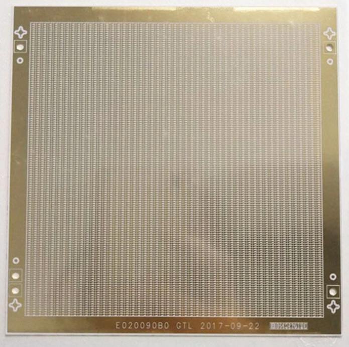
Start with a compatible material system
The substrate, paste chemistry and firing process determine the final film behavior. Printed silver-based, gold or other conductor systems have different cost and assembly implications. Do not specify all of them as equivalent copper alternatives without checking current capacity, soldering and environmental requirements.
Design printed functions deliberately
Printed resistors can be trimmed to a target value, but trimming does not remove temperature coefficient or long-term drift. Crossovers and multilayer printed dielectrics also require qualified thickness and registration rules. Use witness features to characterize the process on the actual substrate.
Specify the finished circuit
Include conductor resistance, resistor tolerance, pad finish and inspection criteria where they affect function. Printed line dimensions alone cannot capture every performance requirement. Ask about firing sequence and repeat firings when conductors, resistors and dielectrics are combined.
Engineering example
A heater pattern must meet power distribution and hot-spot requirements, not just total resistance. Map temperature on an assembled sample with the intended support and cooling conditions.
Before you release the design
- Select substrate and approved paste families together.
- State resistor value, tolerance, TCR and stability needs.
- Confirm soldering or wire-bonding compatibility.
Sources and further technical reading
Manufacturer references support the material and process context. Worked examples and checklists are engineering guidance; they are not test results or supplier guarantees.