
| Region | Top copper fraction | Bottom pattern A | Bottom pattern B |
|---|---|---|---|
| 1 | 90% | 30% | 90% |
| 2 | 90% | 30% | 90% |
| 3 | 30% | 90% | 30% |
| 4 | 30% | 90% | 30% |
| Total coverage | 60% | 60% | 60% |
Balance is a stack-up question
A double-sided ceramic PCB can have equal copper thickness on both faces and still behave asymmetrically. Pattern coverage, the position of large copper islands, ceramic thickness, joining history and assembly attachments all affect the mechanical response. Start by reviewing the whole construction rather than adding a percentage-fill rule to a drawing. The double-sided ceramic circuit guide explains the product format; this review focuses on how to compare the two conductor patterns and turn a concern about bow into a measurable acceptance requirement.
Separate the three kinds of symmetry
Thickness symmetry means matching nominal copper thickness on the two faces. Area symmetry means comparing how much of each face remains metallized after patterning. Spatial symmetry means examining where that copper lies. Two patterns with identical total area can put their copper on opposite ends of the substrate, producing a different local strain and stiffness distribution from aligned patterns. None of these checks alone predicts finished curvature. Treat them as distinct drawing-review questions and record each answer before deciding that a layout is balanced. Include any locally thinned or structured copper features in the review.
Use a coverage map as a screening aid
Divide the useful substrate area into a modest grid and calculate the metallized area fraction on each face in every cell. Keep the same grid origin, cell boundaries and exclusions for both sides. Record top fraction fT, bottom fraction fB, and the difference fT minus fB. Repeat the comparison with a shifted or finer grid around large transitions so that a convenient cell boundary does not conceal a concentrated mismatch. This map is an engineering screening method, not a standardized flatness predictor. It helps identify where a supplier should examine the artwork more closely and makes layout revisions easier to compare.
Worked example: equal totals can hide local mismatch
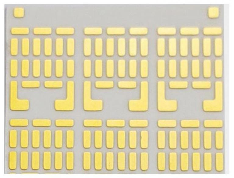
Consider a hypothetical 40 by 30 mm substrate divided into four equal 300 mm² regions. Top-side coverage fractions are 0.90, 0.90, 0.30 and 0.30; bottom-side fractions are 0.30, 0.30, 0.90 and 0.90. Both sides contain 720 mm² of copper, so total coverage is 60% on each face. Yet every region differs by 60 percentage points. A second bottom pattern of 0.90, 0.90, 0.30 and 0.30 has exactly the same total copper but matches the top coverage region by region. This does not establish that the second board will meet a bow limit; it shows why the total area alone is insufficient evidence.
Compare copper volume without treating it as a stress model
For uniform copper thickness, multiply each region's copper area by the corresponding thickness to compare conductor volume. With 0.30 mm top copper and 0.20 mm bottom copper in the example, equal 720 mm² coverage corresponds to 216 and 144 mm³ of copper. Area matching therefore does not produce volume matching. Conversely, redistributing area to equalize volume can create local asymmetry or interfere with the circuit. This simple arithmetic neglects elastic properties, temperature dependence, residual stress and the neutral axis. Use it to expose inconsistent assumptions, then request a stack-specific assessment. The copper-thickness guide covers the associated electrical and manufacturing trade-offs.
Do not confuse ceramic CTE with the finished assembly
Vincotech explicitly distinguishes the thermal expansion of a complete DCB construction from that of its ceramic alone, noting dependence on ceramic and conductor thicknesses. Rogers likewise describes copper-clad substrate behavior separately from bare-ceramic reference properties. Consequently, selecting a low-CTE ceramic is not a substitute for evaluating the metallized part. Add die attachment, a baseplate, solder or sintered joints and the mounting arrangement, and the constraint system changes again. Review the stack-up definition with the supplier using the actual layer sequence and manufacturing state rather than a single material-table number.
Make proposed balancing copper electrically intentional
A suggested copper island is still a conductor. Identify whether it is connected to a defined potential, intentionally floating or removed. Review its relationship to exposed edges, fastening features, nearby terminals and the operating circuit. Do not add metal merely to improve a coverage statistic when it creates an unresolved electrical condition or obstructs assembly. Keep bonding, soldering and inspection areas usable. When a balancing change affects isolation geometry, return to the project-specific creepage and clearance review rather than assuming that unused copper is electrically harmless.
Specify the measurement state for bow and flatness
A useful drawing identifies the datum, inspected surface, support method, temperature, measurement area and process state. A free substrate before assembly is not the same object as a clamped board after soldering. Decide whether the requirement applies to the ceramic outline, a copper attachment surface or a local die-attach region, and state how an edge or patterned gap is treated. Ask for the supplier's proposed measurement method and realistic capability before choosing a limit. Avoid copying a flatness value from a different size or construction. Keep initial incoming inspection and post-assembly acceptance separate when both matter.
Validate the layout revision with a controlled comparison
Preserve the original artwork revision and compare it with the proposed change using the same ceramic grade, layer thicknesses, joining route, finish and measurement method. Record the full map or profile instead of only a pass/fail label; the location of distortion can matter as much as its maximum value. Include relevant assembly thermal exposure and mounting conditions in qualification. If cycling is part of the operating requirement, consult the thermal-cycling guide and define failure criteria independently of room-temperature flatness. A layout change is supported when repeatable measurements and assembly performance improve, not simply when a CAD fill percentage looks more symmetric.
Engineering example
Each of the four hypothetical regions has area 300 mm². Top copper area is 300 × (0.9 + 0.9 + 0.3 + 0.3) = 720 mm². Both bottom patterns have the same area. Pattern A has large local coverage differences; pattern B matches the regional fractions. This is a geometry comparison, not a curvature calculation or supplier limit.
Before you release the design
- Review thickness, area and spatial symmetry separately.
- Record electrical intent for every proposed balancing island.
- Specify flatness datum, support, temperature and process state.
- Compare complete stack-ups with controlled artwork revisions.
- Use measured assembly performance rather than a generic copper-fill percentage as the acceptance basis.
Sources and further technical reading
Manufacturer references support the material and process context. Worked examples and checklists are engineering guidance; they are not test results or supplier guarantees.