
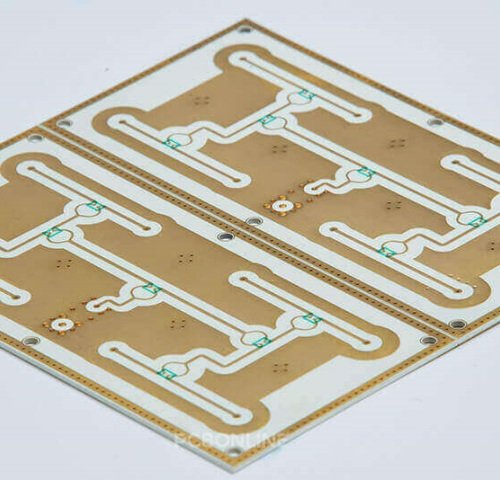
Separate backside copper from a second circuit
A continuous backside plane may be intended for heat spreading or attachment rather than signal routing. State its electrical potential and insulation role. If both faces carry circuits, specify their alignment and any cross-face connections.
Define interconnection and inspection
Plated holes, filled vias and external connections have different limits. The supplier must confirm hole formation, metallization and continuity for the actual ceramic thickness. Avoid importing FR-4 through-hole assumptions into a ceramic process.
Review copper balance and electrical isolation
Top and bottom coverage influence warpage and stress, while ceramic thickness and edge geometry influence insulation. Check both electrical and mechanical consequences of changing the back pattern. Include the final mounting structure in thermal and reliability evaluation.
Engineering example
Removing backside copper to create a clearance region may change local stress and thermal spreading. Revisit the model and supplier review rather than treating it as a cosmetic artwork edit.
Before you release the design
- Identify the function and potential of each face.
- Specify interconnect geometry and test requirements.
- Review top/bottom copper coverage.
Sources and further technical reading
Manufacturer references support the material and process context. Worked examples and checklists are engineering guidance; they are not test results or supplier guarantees.